Chapter 3 3-11
Adjustments and Correction Constants
RF Output Power Correction Constants (Test 47)
RF Output Power Correction Constants (Test 47)
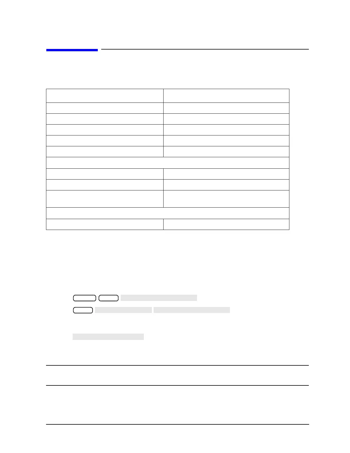
Required Equipment and Tools
Analyzer warm-up time: 30 minutes.
This procedure adjusts several correction constants that can improve the output power
level accuracy of the internal source. They are related to the power level, power slope,
power slope offset, and the ALC roll-off factors among others.
1. If you just completed “Sampler Magnitude and Phase Correction Constants (Test 53),”
start at step 8 in this procedure.
2. Press .
3. Press . The default power meter
address is 13. Refer to the power meter manual as required to observe or change its
GPIB address.
4. Press to toggle between the 438A/437 and 436A power meters.
Choose the appropriate model number. (Use the 438A/437 selection if the power meter
is an E4419B or E4418B.)
NOTE If you are using the 438A power meter, connect the 8482A power sensor to
channel A, and the 8481A power sensor to channel B.
Description HP/Agilent Part or Model Number
Power Meter 436A/437B/438A or E4418B/4419B
GPIB Cable 10833A
Antistatic Wrist Strap 9300-1367
Antistatic Wrist Strap Cord 9300-0980
Static-control Table Mat and Ground Wire 9300-0797
Additional Equipment for 50Ω Analyzers
Power Sensor 8482A
Power Sensor (for Option 006 analyzers) 8481A
Adapter APC-7 to Type-N (f)
(for 8753ES only)
11524A
Additional Equipment for 75Ω Analyzers
Power Sensor 8483A Option H03
Preset Local
Local

 Loading...


