2-28 Chapter 2
System Verification and Performance Tests
Agilent 8753ES System Verification and Performance Tests
5. Minimum R Channel Level
This test confirms that phase lock can be achieved at a specified minimum R channel input
power. Power from the analyzer’s output port is fed into the R channel receiver using the
input found on the front panel. Observations are made for proper phase lock conditions.
Analyzer warm-up time: 30 minutes
Specifications
Required Equipment
Procedure
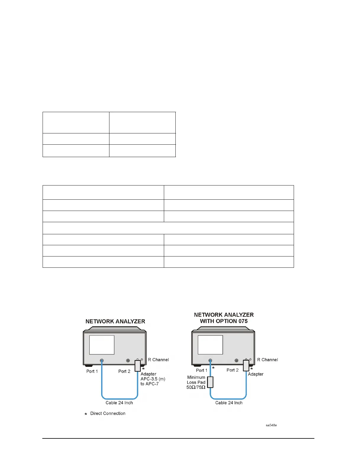
1. Connect the equipment as shown in Figure 2-13.
Figure 2-13 Minimum R Channel Level Test Setup
Frequency Range Minimum R Channel
Level
300 kHz to 3 GHz < −35 dBm
3 GHz to 6 GHz
a
a. Only for analyzers with Option 006.
< −30 dBm
Description HP/Agilent Part or Model Number
Adapter: APC-3.5 (m) to APC-7 1250-1746
Cable: APC-7, 24-inch 8120-4779
Required Equipment for 75Ω Analyzers (Option 075)
Minimum Loss Pad: 50Ω to 75Ω 11852B
Cable: 50Ω Type-N, 24-inch 8120-4781
Adapter: APC-3.5 (m) to Type-N (f) 1250-1750

 Loading...


