Chapter 5 5-11
Power Supply Troubleshooting
If the Red LED of the A15 Is ON
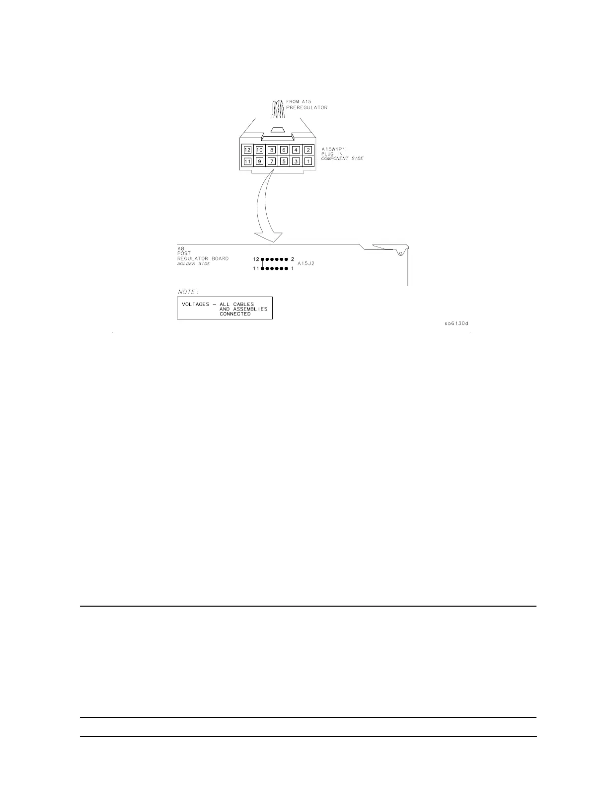
Figure 5-6 A15W1 Plug Detail
Check for a Faulty Assembly
This procedure checks for a faulty assembly that might be shutting down the A15
preregulator via one of the following lines (also refer to Figure 5-1):
• A15W1 connecting to the A8 post regulator
• the +5VCPU line through the motherboard
• the +5VDIG line through the motherboard
Do the following:
1. Switch off the analyzer.
2. Ensure that A15W1 is reconnected to A8. (Refer to Figure 5-5.)
3. Remove or disconnect the assemblies listed in Table 5-3 one at a time and in the order
shown. The assemblies are sorted from most to least accessible. Table 5-3 also lists any
associated assemblies that are supplied by the assembly that is being removed. After
each assembly is removed or disconnected switch on the analyzer and observe the red
LED on A15.
CAUTION • Always switch off the analyzer before removing or disconnecting
assemblies.
• When extensive disassembly is required, refer to Chapter 14 , “Assembly
Replacement and Post-Repair Procedures.”
• Refer to Chapter 13 , “Replaceable Parts,” to identify specific cables and
assemblies that are not shown in this chapter.

 Loading...


