7-12 Chapter 7
Source Troubleshooting
Phase Lock Error
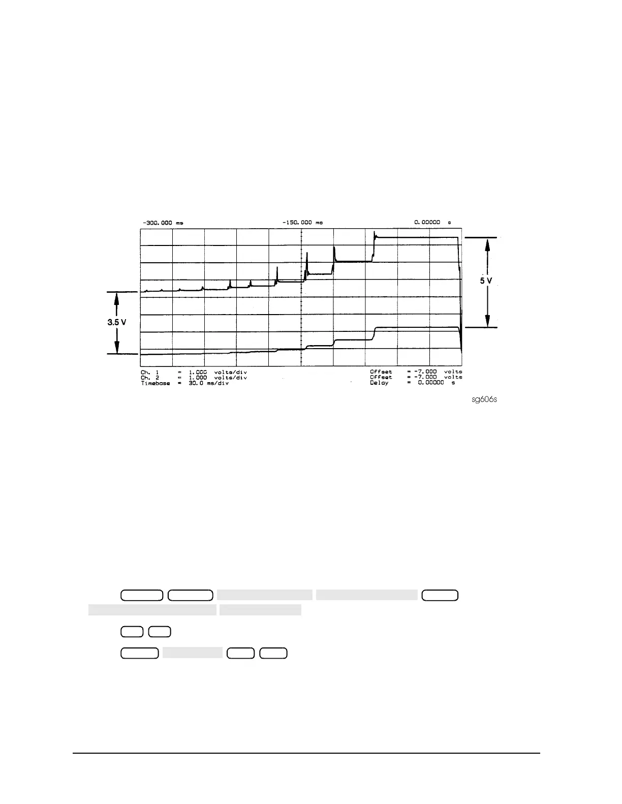
3. Monitor the two YO coil drive lines. In source tune mode, the voltage difference should
vary from approximately 3.5 to 5.0 volts as shown in Figure 7-7.
• If the voltages are not correct, replace the faulty A11 assembly.
• If the output signals from the A11 assembly are correct, replace the faulty A3 source
assembly.
• If neither the A11, nor the A3 assembly is faulty, continue with the next check.
Figure 7-7 YO− and YO+ Coil Drive Voltage Differences with SOURCE PLL OFF
A12 Reference Check
The signals are evaluated with pass/fail checks. The most efficient way to check the A12
frequency reference signals is to use the analog bus while referring to Table 7-2.
Alternatively, you can use an oscilloscope, while referring to Table 7-3 and Figure 7-8
through Figure 7-14. If any of the observed signals differs from the figures, there is a 90%
probability that the A12 assembly is faulty. Either consider the A12 assembly defective or
perform the “A12 Digital Control Signals Check” on page 7-18.
Both of these procedures are described ahead.
Analog Bus Method
1. Press
to switch on the analog bus and its counter.
2. Press to count the frequency of the 100 kHz signal.
3. Press . Verify that the counter reading (displayed on
the analyzer next to cnt:) matches the corresponding 100 kHz value for the CW
frequency. (Refer to Table 7-2.)
Preset System
Meas
21 x1
Menu
500
 Loading...


