Chapter 7 7-11
Source Troubleshooting
Phase Lock Error
YO Coil Drive Check with Analog Bus
NOTE If the analog bus is not functional, perform the “YO Coil Drive Check with
Oscilloscope” on page 7-11.
1. Press
.
2. Then press . This
keystroke sequence lets you check the pretune DAC and the A11 output to the YO coil
drive by monitoring the 1 V/GHz signal at analog bus node 16.
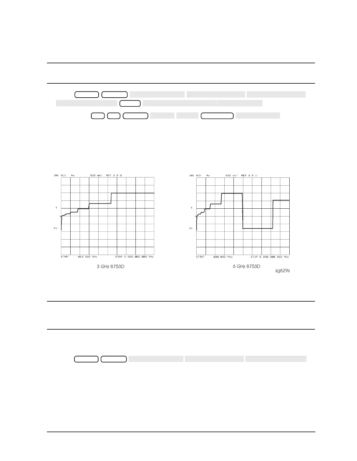
3. Compare the waveform to Figure 7-6. If the waveform is incorrect, the A11 phase lock
assembly is faulty.
Figure 7-6 1 V/GHz at Analog Bus Node 16 with Source PLL Off.
YO Coil Drive Check with Oscilloscope
NOTE Use the large extender board for easy access to the voltage points. The
extender board is included with the 8753 Tool Kit. See Chapter 13 ,
“Replaceable Parts,” for part numbers and ordering information.
1. Connect oscilloscope probes to A11P1-1 and A11P1-2. The YO coil drive signal is
actually two signals whose voltage difference drives the coil.
2. Press to
operate the analyzer in a swept open loop mode.
Preset System
Meas
16 x1
Scale Ref
Preset System
 Loading...


