7-10 Chapter 7
Source Troubleshooting
Phase Lock Error
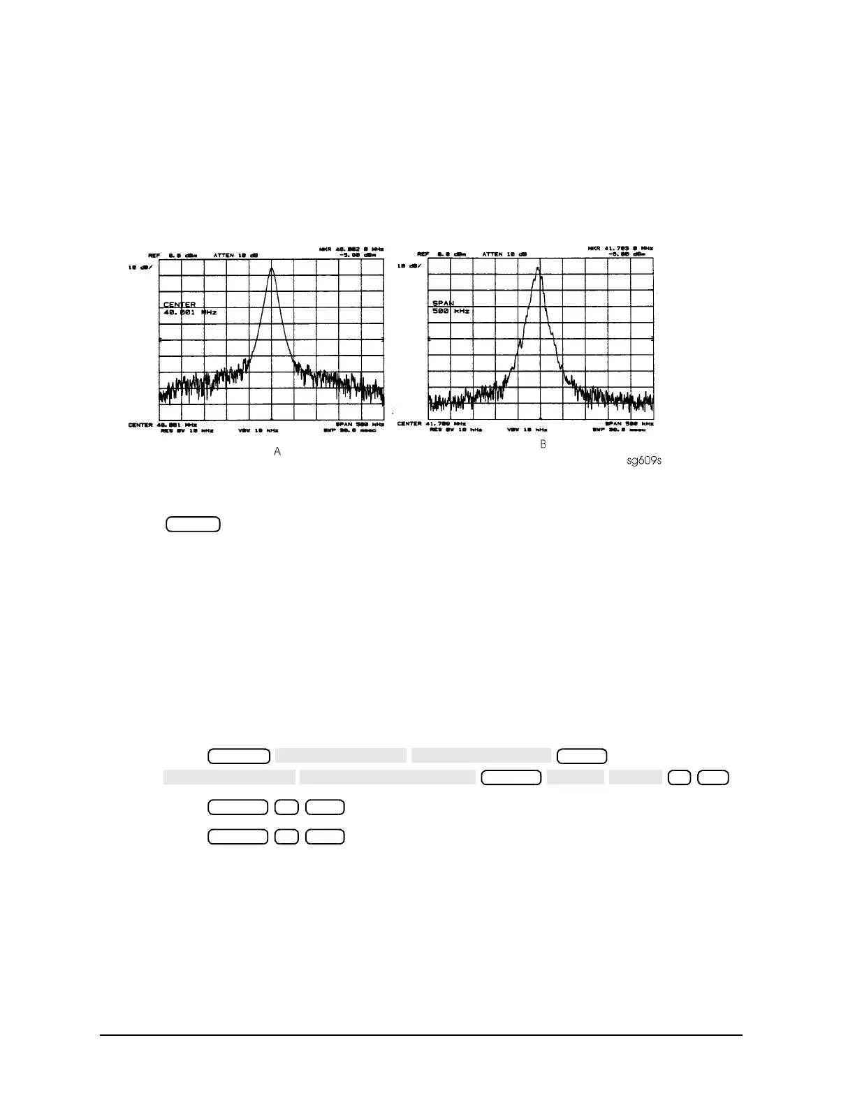
6. The signal observed on the spectrum analyzer will appear jittery as in Figure 7-5 (B),
not solid as in Figure 7-5 (A). This is because in SRC TUNE mode the output is not
phase locked.
Figure 7-5 Phase Locked Output Compared to Open Loop Output in SRC Tune
Mode
7. Press to vary the power and check for corresponding level changes on the test
instrument. (A power change of 20 dB will change the voltage observed on the
oscilloscope by a factor of ten.)
8. Note the results of the frequency and power changes:
• If the frequency and power output changes are correct, skip ahead to “A12 Reference
Check” on page 7-12.
• If the frequency changes are not correct, continue with “YO Coil Drive Check with
Analog Bus” on page 7-11.
• If the power output changes are not correct, check analog bus node 3 by performing
the following steps:
a. Press
.
b. Press . The marker should read approximately 434 mU.
c. Press . The marker should read approximately 646 mU.
Power
System
Meas
Format
3 x1
Marker 2 G/n
Marker 4 G/n

 Loading...


