Chapter 8 8-11
Receiver Troubleshooting
Troubleshooting When One or More Inputs Look Good
Check 2nd LO Signal at Sampler/Mixer
Check the 2nd LO signal at the pins identified in Table 8-3. Refer to the “A12 Reference
Check” on page 7-12 for analog bus and oscilloscope checks of the 2nd LO and waveform
illustrations. Table 8-3 identifies the signal location at the samplers and the A12 assembly.
If the 2nd LO is good at the sampler/mixer, the sampler/mixer assembly is faulty.
Otherwise, troubleshoot the A12 assembly and associated signal path.
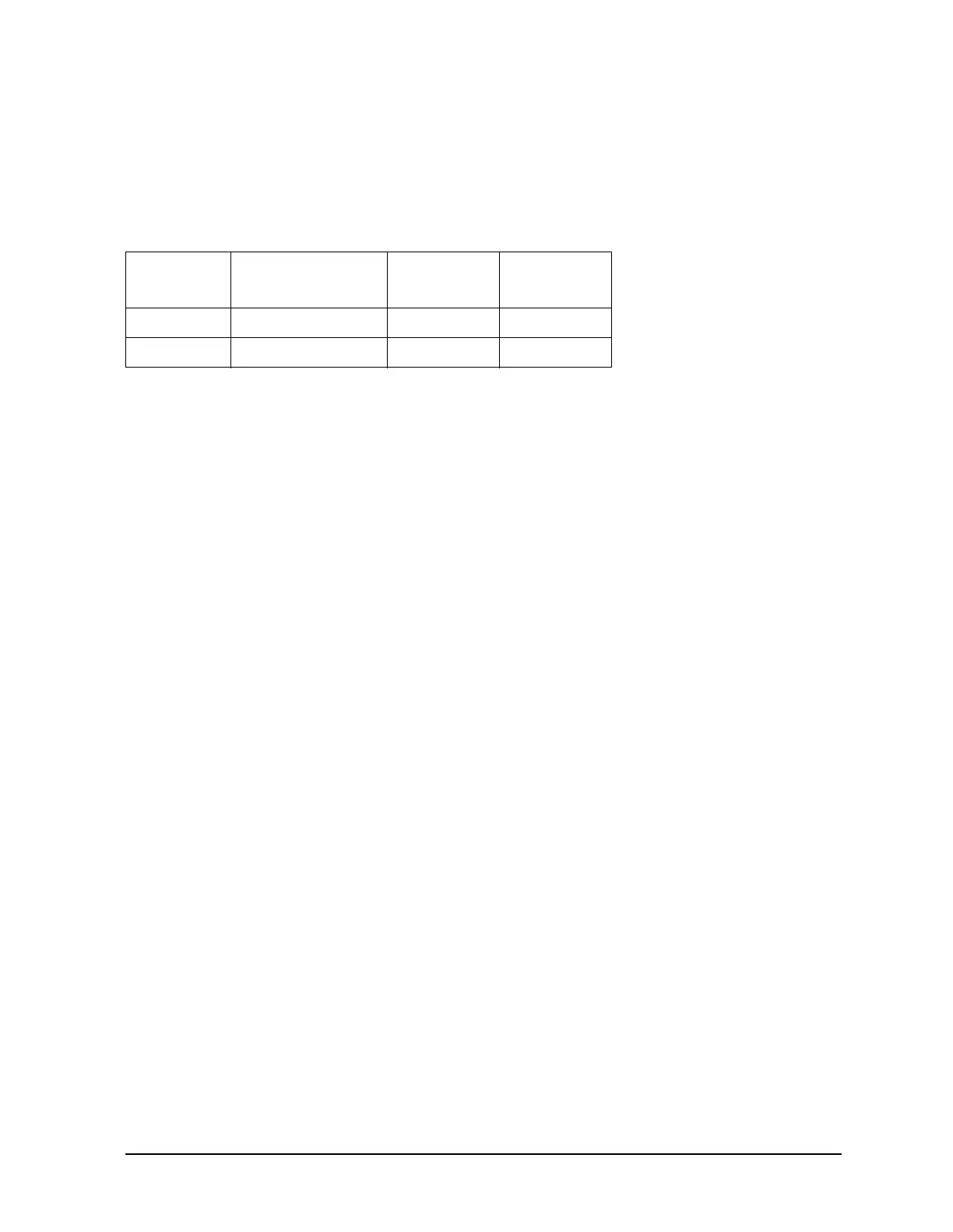
Table 8-3 2nd LO Locations
Mnemonic Description Sampler
Location
Signal Source
2nd LO 1 2nd LO (0 degrees) A4/5/6 P1-11 A12P1-2, 32
2nd LO 2 2nd LO (−90 degrees) A4/5/6 P1-4 A12P1-4, 34
 Loading...


