7-6 Chapter 7
Source Troubleshooting
Phase Lock Error
Phase Lock Error
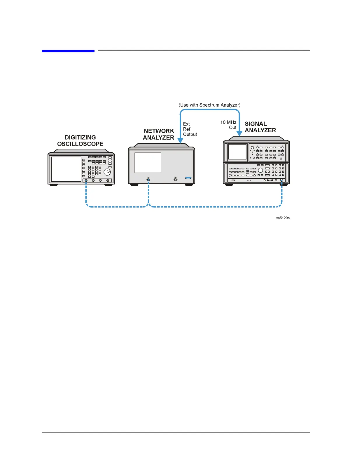
Figure 7-1 Basic Phase Lock Error Troubleshooting Equipment Setup
Troubleshooting tools include the assembly location diagram and phase lock diagnostic
tools. The assembly location diagram is on the underside of the instrument top cover. The
diagram shows major assembly locations and RF cable connections. The phase lock
diagnostic tools are explained in the “Source Group Troubleshooting Appendix” on
page 7-30 and should be used to troubleshoot phase lock problems. The equipment setup
shown in Figure 7-1 can be used throughout this chapter.
Phase Lock Loop Error Message Check
Phase lock error messages may appear as a result of incorrect pretune correction
constants. To check this possibility, perform the pretune correction constants routine.
The four phase lock error messages, listed below, are described in the “Source Group
Troubleshooting Appendix” on page 7-30.
• NO IF FOUND: CHECK R INPUT LEVEL
• NO PHASE LOCK: CHECK R INPUT LEVEL
• PHASE LOCK CAL FAILED
• PHASE LOCK LOST

 Loading...


