Chapter 7 7-7
Source Troubleshooting
Phase Lock Error
1. Make sure the A9 CC switch is in the ALTER position:
a. Remove the power line cord from the analyzer.
b. Set the analyzer on its side.
c. Remove the two corner bumpers from the bottom of the instrument with a T-15
TORX screwdriver.
d. Loosen the captive screw on the bottom cover’s back edge.
e. Slide the cover toward the rear of the instrument.
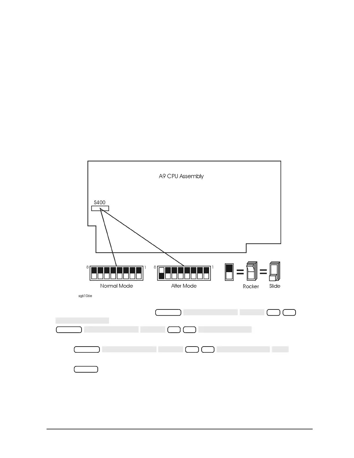
f. Set the switch to the ALTER position as shown in Figure 7-2.
g. Replace the bottom cover, corner bumpers, and power cord.
Figure 7-2 Switch Positions on the A9 CPU
2. Switch on the analyzer and press
to generate new analog bus correction constants. Then press
to generate default
pretune correction constants.
Press to
generate new pretune correction constants.
3. Press and observe the analyzer display:
• No error message: set the A9 CC switch to the NORMAL position. Then refer to
“Post-Repair Procedures” on page 14-53 to verify operation.
• Error message visible: continue with “A4 Sampler/Mixer Check”.
System
46 x1
System
45 x1
System
48 x1
Preset

 Loading...


