2-56 Chapter 2
System Verification and Performance Tests
Agilent 8753ES System Verification and Performance Tests
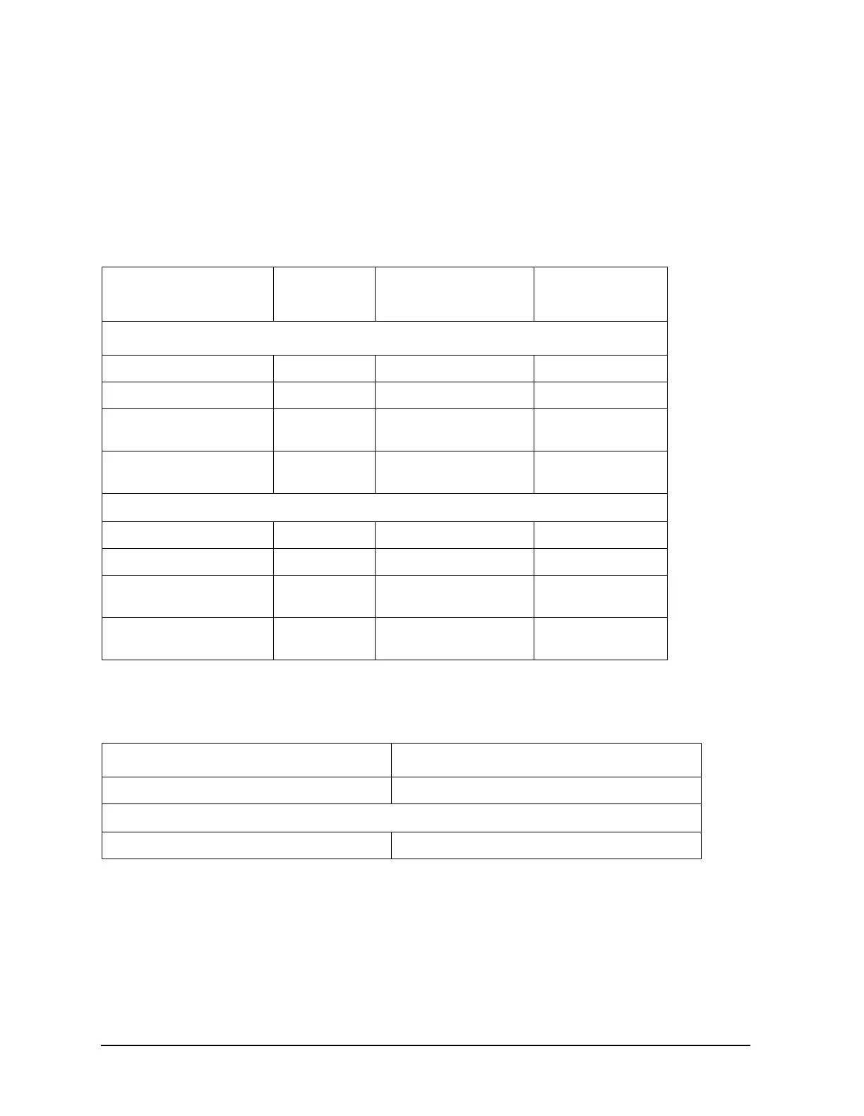
10. System Trace Noise
Ratio measurements A/R and B/R are made at 3 GHz and 6 GHz to determine the
variability of the analyzer’s measurement data. IF bandwidths of 3 kHz and 10 Hz are
used for the test.
Analyzer warm-up time: 30 minutes
Specifications
Required Equipment
Procedure
1. Connect the equipment as shown in Figure 2-33.
Frequency Range Ratio System Trace Noise
(Magnitude
a
)
a. Trace noise is defined for a transmission measurement in CW mode using a
“through” cable having 0 dB loss, with the source set to +5 dBm, and no averaging.
System Trace
Noise (Phase
a
)
IF Bandwidth = 10 Hz
300 kHz to 3 GHz A/R <0.001 dB rms <0.006 °rms
300 kHz to 3 GHz B/R <0.001 dB rms <0.006 °rms
3 GHz to 6 GHz
(Option 006)
A/R <0.002 dB rms <0.012 °rms
3 GHz to 6 GHz
(Option 006)
B/R <0.002 dB rms <0.012 °rms
IF Bandwidth = 3 kHz
300 kHz to 3 GHz A/R <0.006 dB rms <0.038 °rms
300 kHz to 3 GHz B/R <0.006 dB rms <0.038 °rms
3 GHz to 6 GHz
(Option 006)
A/R <0.010 dB rms <0.070 °rms
3 GHz to 6 GHz
(Option 006)
B/R <0.010 dB rms <0.070 °rms
Description HP/Agilent Part Number
Cable: APC-7, 24-inch 8120-4779
Additional Equipment for 75Ω Analyzers
Cable: 75Ω, Type-N, 24-inch 8120-2408
 Loading...


