3-20 Chapter 3
Adjustments and Correction Constants
Sampler Magnitude and Phase Correction Constants (Test 53)
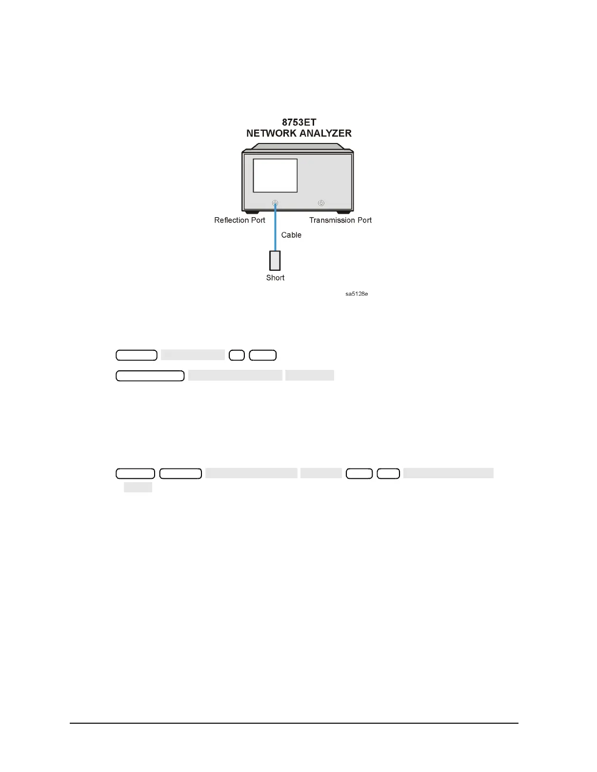
5. Attach a type-N cable and a short to the Reflection port as shown in Figure 3-6.
Figure 3-6 Second Connection for Insertion Loss Measurement (8753ET)
6. Press .
7. Press .
8. Note the marker reading and divide it by 2. Record this calculated value as the
insertion loss of the cable. It will be used later in this procedure. Proceed to “Sampler
Correction Constants Routine,” next.
Sampler Correction Constants Routine
1. Press and
answer at the prompt.
2. The analyzer displays:
CONNECT <3 GHz SENSOR A TO PORT 1 (8753ES)
or
CONNECT <3 GHz SENSOR A TO REFL PORT (8753ET)
Make the connections as shown in Figure 3-7, using the 8482A power sensor.
Marker
1
Preset System
53 x1

 Loading...


