7-14 Chapter 7
Source Troubleshooting
Phase Lock Error
Oscilloscope Method
You need not use the oscilloscope method unless the analog bus is non-functional or any of
the signals fail the specifications listed in Table 7-2.
If the analog bus is non-functional or the previous check has revealed questionable signals,
observe the signals with an oscilloscope. Table 7-3 identifies a convenient test point and a
plot for the five signals listed.
100 kHz Pulses
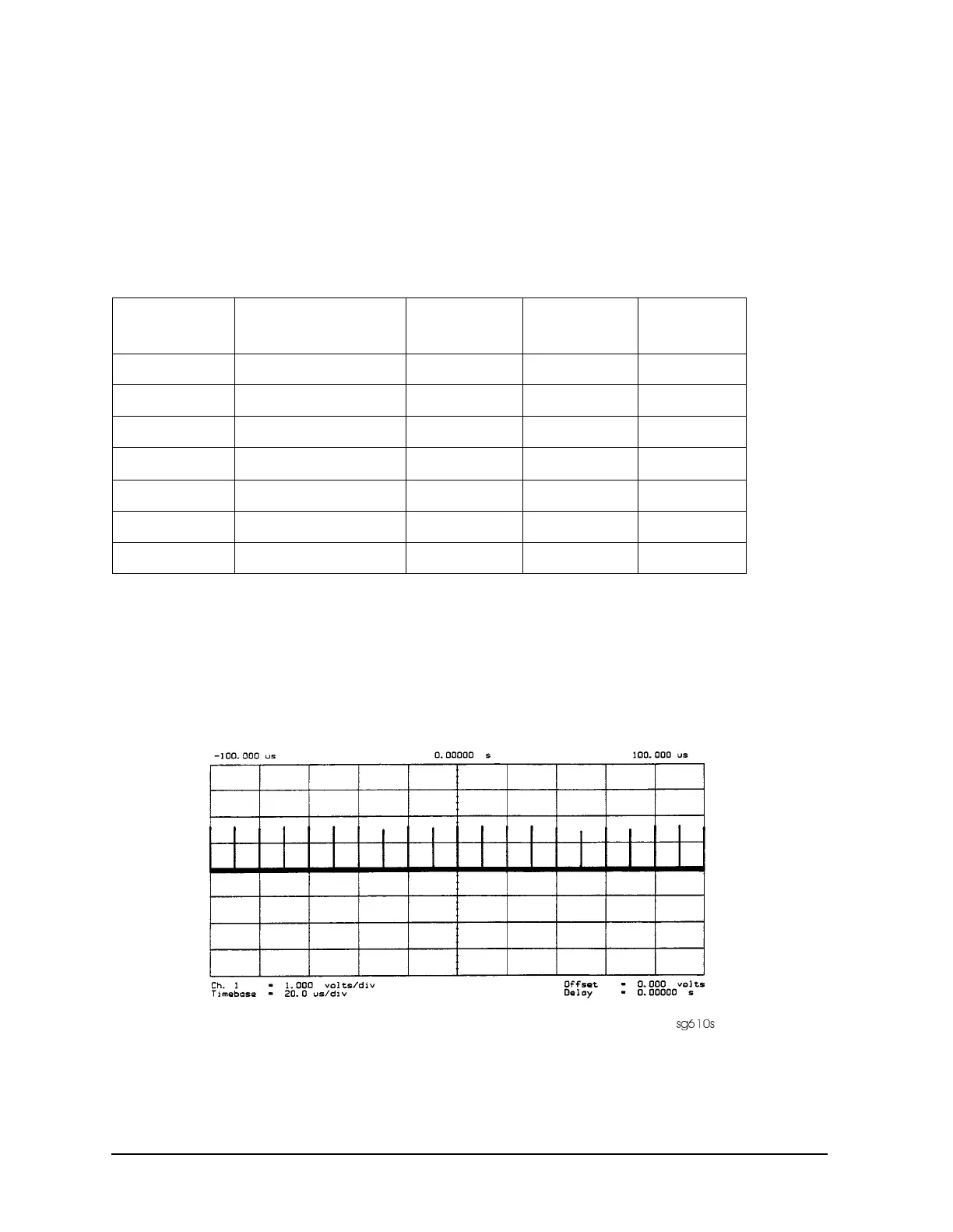
The 100 kHz pulses are very narrow and typically 1.5 V in amplitude. You may have to
increase the oscilloscope intensity to see these pulses. (See Figure 7-8.)
Figure 7-8 Sharp 100 kHz Pulses at A13TP5 (any frequency)
Table 7-3 A12 Reference Frequencies
Mnemonic Signal Description Location See Figure Analyzer
Setting
FN100kHzREF 100 kHz Reference A13TP5
Figure 7-8
any
REF Phase Lock Reference A11TP9
Figure 7-9
≥16 MHz CW
REF Phase Lock Reference A11TP9
Figure 7-10
5 MHz CW
FN LO
a
*
a. Not an A12 signal, but required for A12 low band operation.
Fractional-N LO A14J2
Figure 7-11
10 MHz CW
4MHz REF 4 MHz Reference A12TP9
Figure 7-12
any
2ND LO+/− Second LO A12P1-2,4
Figure 7-13
≥16 MHz CW
2ND LO+/− Second LO A12P1-2,4
Figure 7-14
14 MHz CW

 Loading...


