7-16 Chapter 7
Source Troubleshooting
Phase Lock Error
FN LO at A12 Check
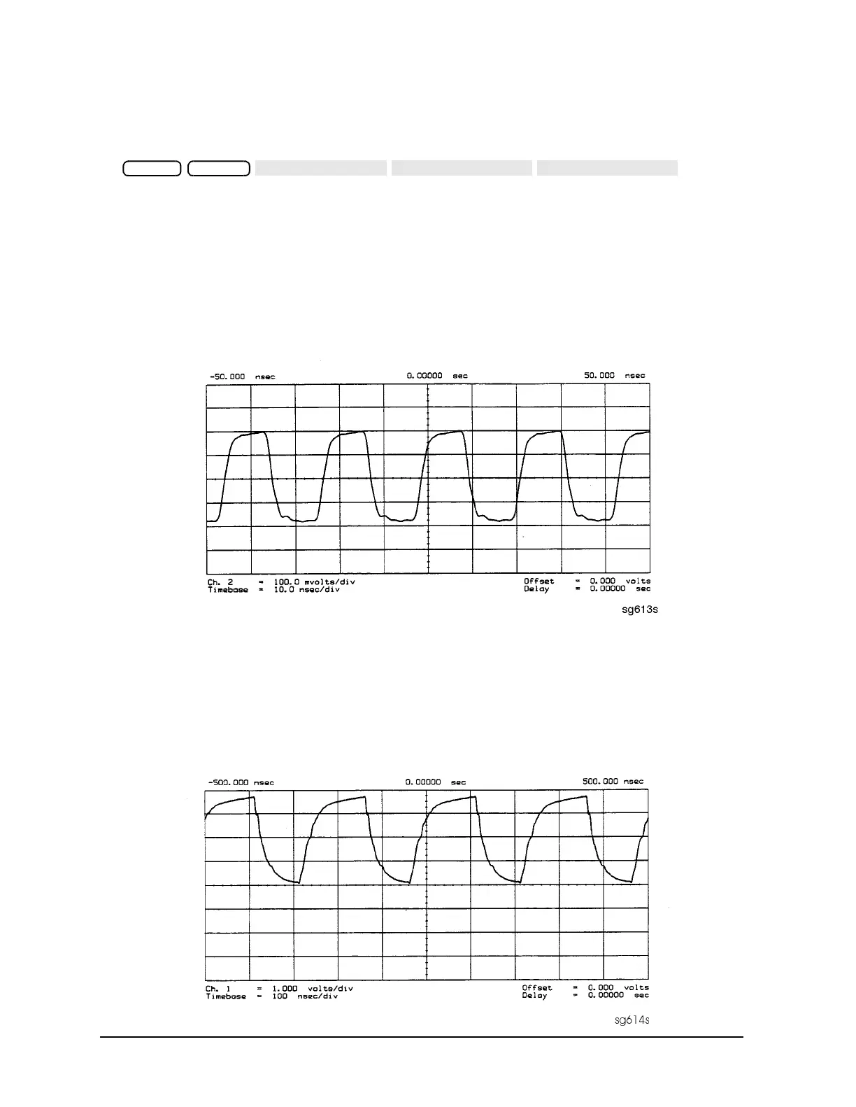
1. Use an oscilloscope to observe the FN LO from A14 at the cable end of A14J2. Press
to
switch on the fractional-N service mode.
2. Use the front panel knob to vary the frequency from 30 to 60 MHz. The signal should
appear similar to Figure 7-11. The display will indicate 10 to 60.8 MHz.
• If the FN LO signal is good, the A12 assembly is faulty.
• If the FN LO signal is not good, skip ahead to “A13/A14 Fractional-N Check” on
page 7-20.
Figure 7-11 Typical FN LO Waveform at A12J1
4 MHz Reference Signal
This reference signal is used to control the receiver. If faulty, this signal can cause
apparent source problems because the CPU uses receiver data to control the source. At
A12TP9 it should appear similar to Figure 7-12.
Figure 7-12 4 MHz Reference Signal at A12TP9 (Preset)
Preset System

 Loading...


