7-18 Chapter 7
Source Troubleshooting
Phase Lock Error
A12 Digital Control Signals Check
Several digital control signals must be functional for the A12 assembly to operate properly.
Check the control lines listed in Table 7-1 with the oscilloscope in the high input
impedance setting.
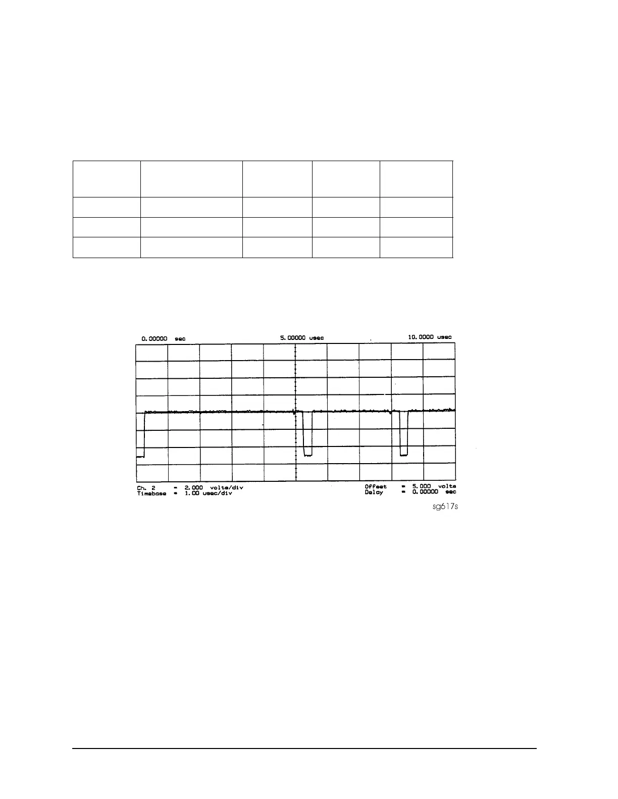
L ENREF Line This is a TTL signal. To observe it, trigger on the negative edge. In
preset state, the signal should show activity similar to Figure 7-15.
Figure 7-15 L ENREF Line at A12P2-16 (Preset)
L HB and L LB Lines These complementary signals toggle when the instrument
switches from low band to high band as illustrated by Figure 7-16.
Table 7-4 A12-Related Digital Control Signals
Mnemonic Signal Description Location See Figure Analyzer
Setting
L ENREF L=Reference Enable A12P2-16
Figure 7-15
Preset
L HB L=High Band A12P2-32
Figure 7-16
Preset
L LB L=Low Band A12P1-23
Figure 7-16
Preset

 Loading...


