12-16 Chapter 12
Theory of Operation
Source Theory Overview
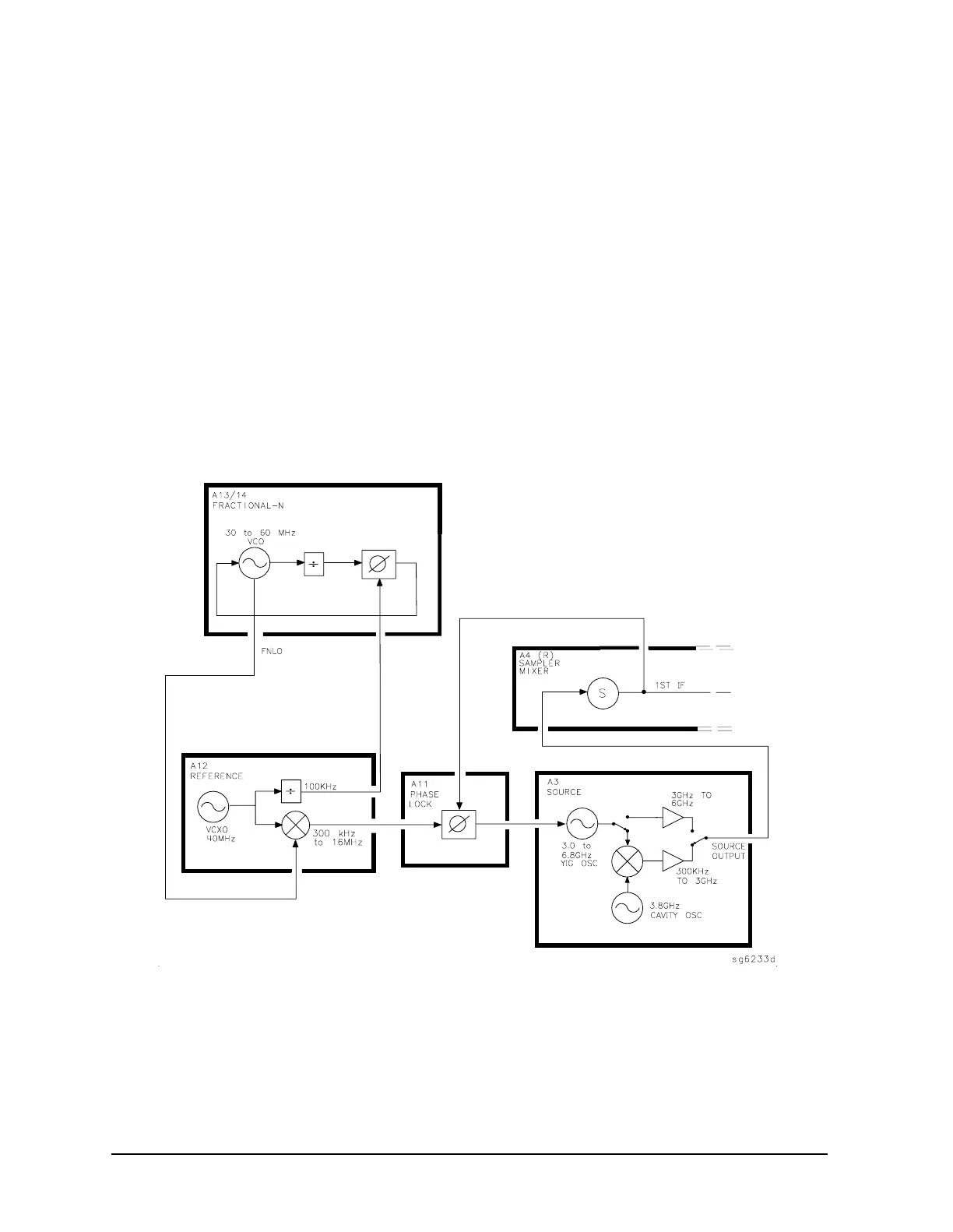
4. The signal from the source is fed back (1st IF) to the phase comparator. The
source output signal passes directly through the sampler in the A4 assembly, because
the sampler is biased on. The signal (1st IF) is fed back unaltered to the phase
comparator in the A11 phase lock assembly. The other input to the phase comparator is
the heterodyned reference signal from the A12 assembly. Any frequency difference
between these two signals produces a proportional error voltage.
5. A tuning signal (YO DRIVE) tunes the source and phase lock is achieved. The
error voltage is used to drive the A3 source YIG oscillator to bring the YIG closer to the
reference frequency. The loop process continues until the source frequency and the
reference frequency are the same, and phase lock is achieved.
6. A synthesized sub sweep is generated. The source tracks the synthesizer.
When lock is achieved at the start frequency, the synthesizer starts to sweep. This
changes the phase lock reference frequency, and causes the source to track at a
difference frequency 40 MHz below the synthesizer.
Figure 12-4 Low Band Operation of the Source

 Loading...


