Home
Agilent Technologies
Measuring Instruments
8753ET
Service Guide
Page 566
Agilent Technologies 8753ET - Page 566
617 pages
Manual
To Next Page
To Next Page
To Previous Page
To Previous Page
Loading...
Chapter
14
14-
23
Assembly Repl
acem
ent
and P
ost-Repair Procedures
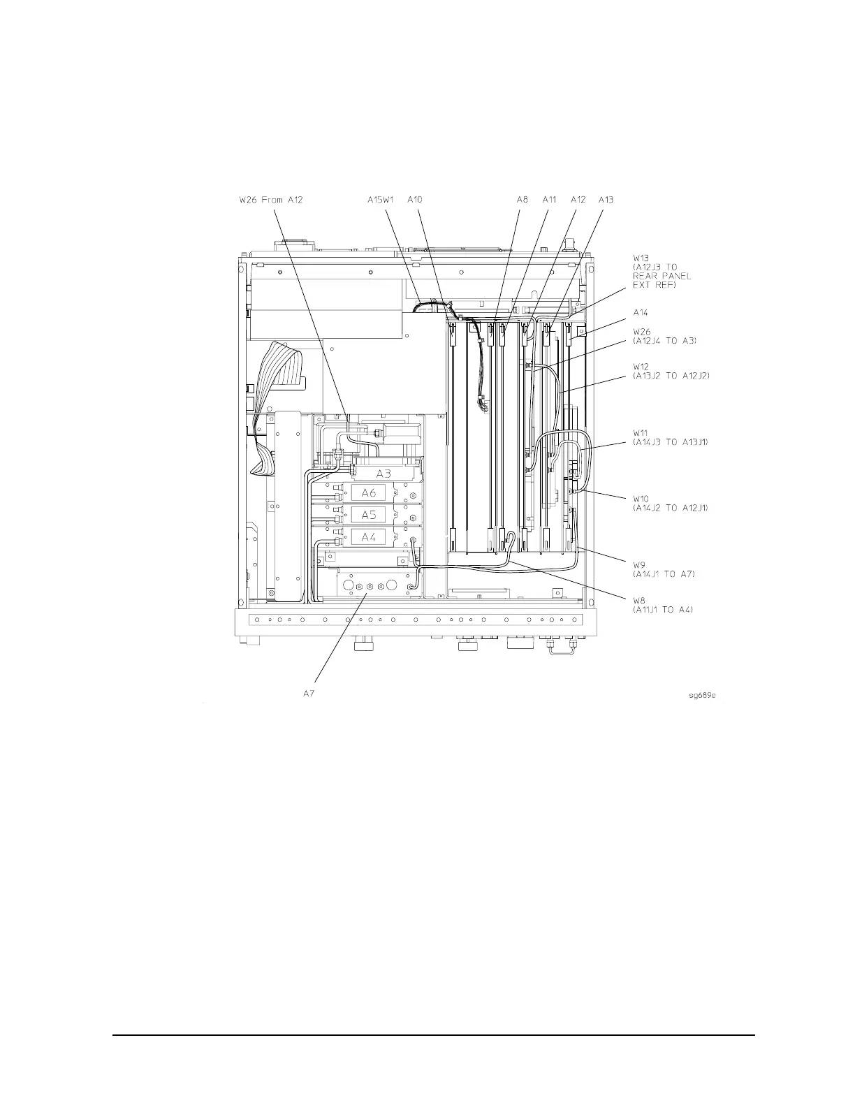
A8,
A10, A11, A12,
A13, A14 Car
d Cage Boards
Figur
e
14-10
Car
d Ca
ge Bo
ard
s: A8, A
10, A1
1, A1
2, A13,
A14
565
567
Table of Contents
Main Page
Warranty Information
2
Safety Notes
3
Required Tools and Equipment
16
Principles of Microwave Connector Care
21
Analyzer Options Available
22
Option 075, 75 Ohm System Impedance (8753ES Only)
23
Service and Support Options
24
Option W54
25
Introduction
28
System Verification Procedure
29
Certificate of Calibration
30
Agilent 8753ES System Verification and Performance Tests
31
ES Performance Tests
39
Test Port Output Frequency Range and Accuracy
40
External Source Mode Frequency Range
43
Test Port Output Power Level Accuracy
45
Test Port Output Power Linearity
48
Minimum R Channel Level
54
Test Port Input Noise Floor Level
58
Test Port Input Frequency Response
62
Test Port Crosstalk
71
Uncorrected Port Performance
76
System Trace Noise
82
Test Port Receiver Magnitude Dynamic Accuracy
85
Test Port Receiver Magnitude Compression
98
Test Port Receiver Phase Compression
101
Test Port Output/Input Harmonics (Analyzers with Option 002)
104
Harmonic Measurement Accuracy (Analyzers with Option 002)
109
Agilent 8753ET System Verification and Performance Tests
113
ET Performance Tests
121
Reflection Test Port Output Frequency Range and Accuracy
122
External Source Mode Frequency Range
124
Reflection Test Port Output Power Level Accuracy
126
Reflection Test Port Output Power Linearity (Analyzers Without Option 004)
128
Reflection Test Port Output Power Linearity (Analyzers with Option 004)
134
Minimum R Channel Level
140
Transmission Test Port Input Noise Floor Level
145
Transmission Test Port Input Frequency Response
148
Test Port Crosstalk
153
Uncorrected Port Performance
157
System Trace Noise
162
Agilent 8753ES Performance Test Records
167
Agilent 8753ET Performance Test Records
187
Post-Repair Procedures
205
A9 Switch Positions
208
Source Default Correction Constants (Test 44)
209
Source Pretune Default Correction Constants (Test 45)
210
Analog Bus Correction Constants (Test 46)
211
Source Pretune Correction Constants (Test 48)
212
RF Output Power Correction Constants (Test 47)
213
IF Amplifier Correction Constants (Test 51)
216
ADC Offset Correction Constants (Test 52)
217
Sampler Magnitude and Phase Correction Constants (Test 53)
218
Power Sensor Calibration Factor Entry
219
Determine the Insertion Loss of the Cable at 1 Ghz (8753ES)
220
Determine the Insertion Loss of the Cable at 1 Ghz (8753ET)
221
Sampler Correction Constants Routine
222
Cavity Oscillator Frequency Correction Constants (Test 54)
228
Spur Search Procedure with a Filter
230
Spurs Search Procedure Without a Filter
231
Serial Number Correction Constants (Test 55)
233
Option Numbers Correction Constants (Test 56)
234
Initialize Eeproms (Test 58)
235
EEPROM Backup Disk Procedure
236
Correction Constants Retrieval Procedure
237
Loading Firmware
238
Loading Firmware into a New CPU
240
Fractional-N Frequency Range Adjustment
242
Frequency Accuracy Adjustment
245
High/Low Band Transition Adjustment
249
Fractional-N Spur Avoidance and FM Sideband Adjustment
251
Source Spur Avoidance Tracking Adjustment
254
Unprotected Hardware Option Numbers Correction Constants
256
Sequences for Mechanical Adjustments
257
How to Set up the High/Low Band Transition Adjustments
258
Assembly Replacement Sequence
265
Having Your Analyzer Serviced
266
Step 1. Initial Observations
267
Step 2. Operator's Check
268
Required Equipment and Tools
269
Step 3. GPIB Systems Check
270
If Using an External Disk Drive
271
Step 4. Faulty Group Isolation
272
Power Supply
273
Digital Control
274
Verify Internal Tests Passed
275
Source
276
No Oscilloscope or Power Meter? Try the ABUS
277
Receiver (8753ES)
279
Receiver Error Messages
280
Receiver (8753ET)
281
Receiver Error Messages
283
Accessories
284
Troubleshooting 8753ES Option 014
285
Setup
287
Symptom Example Plots
288
Symptoms
290
Power Supply Troubleshooting
298
Assembly Replacement Sequence
299
Simplified Block Diagram
300
Start here
301
Measure the Post Regulator Voltages
302
If the Green LED of the A15 Is Not on Steadily
303
Check the A8 Post Regulator
304
Verify the A15 Preregulator
306
Check for a Faulty Assembly
307
Check the Operating Temperature
308
Remove A8, Maintain A15W1 Cable Connection
309
Briefly Disable the Shutdown Circuitry
310
Inspect the Motherboard
312
Error Messages
313
Check the Fuses and Isolate A8
314
Fan Troubleshooting
315
Intermittent Problems
316
Digital Control Troubleshooting
319
Digital Control Group Block Diagram
320
Assembly Replacement Sequence
321
CPU Troubleshooting (A9)
322
Checking A9 CPU Red LED Patterns
323
Display Troubleshooting (A2, A18, A19, A27)
324
Troubleshooting a White Display
327
Troubleshooting a Display with Color Problems
328
Front Panel Troubleshooting (A1, A2)
329
Identify the Stuck Key
330
Inspect Cables
332
Run the Internal Diagnostic Tests
333
If the Fault Is Intermittent
335
GPIB Failures
336
Source Troubleshooting
339
Assembly Replacement Sequence
340
Before You Start Troubleshooting
341
Power
342
Phase Lock Error
343
A4 Sampler/Mixer Check
345
A12 Reference Check
349
A13/A14 Fractional-N Check
357
A7 Pulse Generator Check
362
A11 Phase Lock Check
365
Source Group Troubleshooting Appendix
367
Broadband Power Problems
368
Receiver Troubleshooting
371
Assembly Replacement Sequence
372
Receiver Failure Error Messages
373
Troubleshooting When All Inputs Look Bad
374
Check the 4 Mhz REF Signal
375
Check A10 by Substitution or Signal Examination
376
Troubleshooting When One or more Inputs Look Good
378
Check the Trace with the Sampler Correction Constants off
379
Check 2Nd lo Signal at Sampler/Mixer
380
Accessories Troubleshooting
383
Assembly Replacement Sequence
384
Inspect the Accessories
385
Inspect the Error Terms
386
Cable Test
387
Service Key Menus
392
Service Feature Menus
405
Firmware Revision Softkey
430
GPIB Service Mnemonic Definitions
431
Analog Bus Codes
432
Error Messages
433
Error Terms
441
Error Terms Can also Serve a Diagnostic Purpose
442
Error Correction
443
Error Term Descriptions
444
How the Analyzer Works
454
The Built-In Test Set
455
A Close Look at the Analyzer's Functional Groups
456
Power Supply Theory
457
A8 Post Regulator
458
Digital Control Theory
460
A1 Front Panel
462
A18 Display
463
A27 Inverter
464
Source Theory Overview
465
A3 Source
466
Source High Band Operation
468
Source Operation in Other Modes and Features
470
Signal Separation (8753ET)
474
Signal Separation (8753ES)
476
Receiver Theory
478
A4/A5/A6 Sampler/Mixer
480
A10 Digital if
481
Replacing an Assembly
484
Rebuilt-Exchange Assemblies
485
Ordering Information
486
Replaceable Part Listings
488
ET: Major Assemblies, Top
491
ES: Major Assemblies, Top
493
ET: Major Assemblies, Bottom
495
ES: Major Assemblies, Bottom
496
ES Option 014: Major Assemblies and Cables, Bottom
497
ET: Cables, Top
499
ES: Cables, Top
501
ES Option 014: Cables, Top
503
ET: Cables, Bottom
505
ES: Cables, Bottom
507
ET: Cables, Front
509
ES: Cables, Front
511
ET/ES: Cables, Rear
513
ET/ES: Cables, Source
515
ET/ES: Front Panel Assembly, Outside
517
ET/ES: Front Panel Assembly, Inside
519
ET: Rear Panel Assembly
521
ES: Rear Panel Assembly
523
ET/ES: Rear Panel Assembly, Option 1D5
525
ET/ES: Hardware, Top
527
ET: Hardware, Bottom
529
ES: Hardware, Bottom
530
ET/ES: Hardware, Front
531
ET: Hardware, Test Set Deck
532
ES: Hardware, Test Set Deck
533
ET/ES: Hardware, Disk Drive Support
534
ET/ES: Hardware, Memory Deck
535
ET/ES: Hardware, Preregulator
536
ET/ES: Chassis Parts, Outside
537
ET/ES: Chassis Parts, Inside
539
Miscellaneous
540
Replacing an Assembly
546
Procedures Described in this Chapter
547
Line Fuse
548
Covers
549
Front Panel Assembly
551
Front Panel Keyboard and Interface Assemblies (A1, A2)
553
Display, Display Lamp and Inverter Assemblies (A18, A27)
555
Rear Panel Assembly
557
Rear Panel Interface Board Assembly (A16)
559
A3 Source Assembly
561
A4, A5, A6 Samplers and A7 Pulse Generator
563
A8, A10, A11, A12, A13, A14 Card Cage Boards
565
A9 CPU Board
567
A9BT1 Battery
569
A15 Preregulator
571
A17 Motherboard Assembly
573
A19 Graphics Processor
577
A20 Disk Drive Assembly
579
A20 Disk Drive Assembly Replacement
581
Test the Disk-Eject Function, and Adjust if Required
582
A21, A22 Test Port Couplers (8753ES Only)
583
A21 Dual Directional Coupler (8753ET Only)
585
A23 LED Board (8753ES Only)
587
A24 Transfer Switch (8753ES Only)
589
A25 Test Set Interface (8753ES Only)
591
A26 High Stability Frequency Reference (Option 1D5) Assembly
593
B1 Fan Assembly
595
Post-Repair Procedures
596
General Information
599
Shipment for Service
600
Safety Symbols
601
Instrument Markings
602
Safety Considerations
603
Servicing
604
General
605
Other manuals for Agilent Technologies 8753ET
User Guide
479 pages
Configuration Guide
16 pages
Installation And Quick Start Guide
62 pages
Manual Supplement
164 pages
Related product manuals
Agilent Technologies 8753ES
479 pages
Agilent Technologies 8712ET
152 pages
Agilent Technologies 8719ES
478 pages
Agilent Technologies 8719ET
478 pages
Agilent Technologies 8720ES
12 pages
8720E Series
541 pages
Agilent Technologies 8560E
716 pages
Agilent Technologies 8504B
296 pages
Agilent Technologies 8590L
673 pages
Agilent Technologies 8565EC
512 pages
Agilent Technologies 8564EC
512 pages
86140B Series
288 pages