216 Chapter 7
Digital Signal Interface Module
Clock Timing
Clock Timing
This section describes how clocking for the digital data is provided. Clock timing information and diagrams
are supplied for the different port configurations (serial, parallel, or parallel interleaved data transmission)
and phase and skew settings. All settings for the interface module are available on the signal generator user
interface (UI).
Clock and Sample Rates
A sample is a group of bits where the size of the sample is set using the Word Size softkey. The clock is the
signal that tells when the bits of a sample are valid (in a non-transition state). The clock and sample rates are
displayed in the first-level and data setup softkey menus. The clock rate and sample rate are usually the
same. They will differ when serial mode is selected, or when there are multiple clocks per sample.
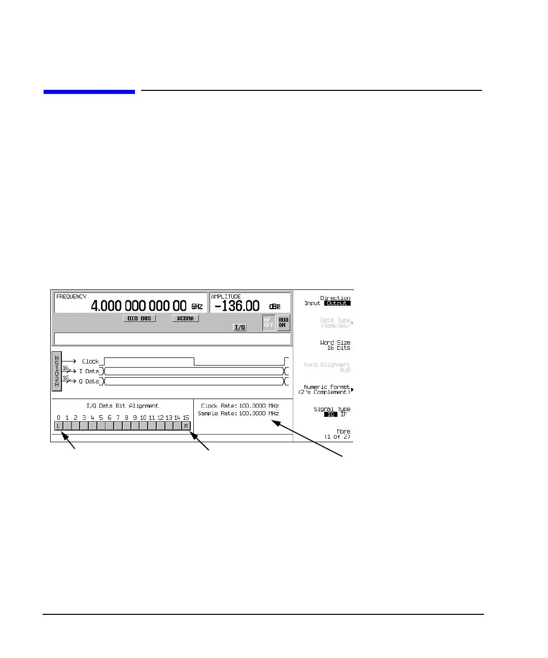
Figure 7-1 Data Setup Menu for a Parallel Port Configuration
The N5102A module clock rate is set using the
Clock Rate softkey and has a range of 1 kHz to
400 MHz. The sample rate is automatically calculated and has a range of 1 kHz to 100 MHz. These ranges
can be smaller depending on logic type, data parameters, and clock configuration.
Maximum Clock Rates
The N5102A module maximum clock rate is dependent on the logic and signal type. Table 7-1 and
Table 7-2 show the warranted rates and the maximum clock rates for the various logic and signal types.
Notice that LVDS in the output mode using an IF signal is the only logic type where the warranted and
maximum rates are the same.
Clock and sample rates
Least significant bit
Most significant bit