168 Chapter 4
Basic Digital Operation
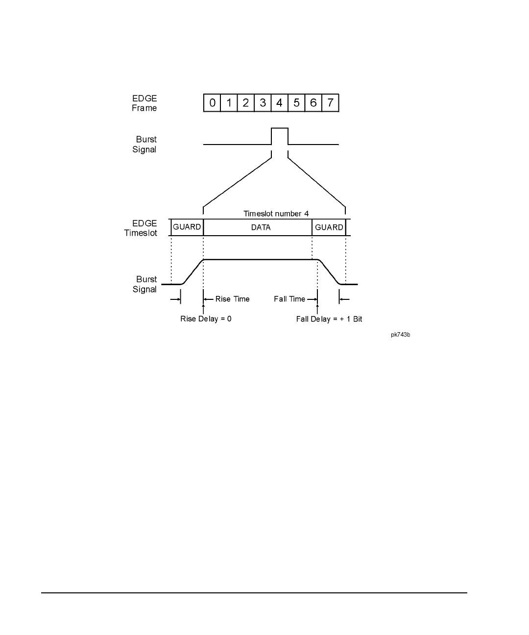
Using Customized Burst Shape Curves
The signal generator firmware computes optimum burst shape based on the settings you’ve chosen for
modulation. You can further optimize burst shape by lining up the data portion with the modulation. For
example, if you’re designing a new modulation scheme, do the following:
• Adjust the modulation and filtering to set the spectrum you want.
• Turn on framing.
• Adjust the burst rise and fall delay and rise and fall time for the timeslots.
If you find that the error vector magnitude (EVM) or adjacent channel power (ACP) increases when you turn
bursting on, you can adjust the burst shape to assist with troubleshooting.
Creating a User-Defined Burst Shape Curve
Using this procedure, you learn how to enter rise shape sample values and mirror them as fall shape values
to create a symmetrical burst curve.
This section teaches you how to perform the following tasks:
• “Accessing the Table Editors” on page 169
• “Entering Sample Values” on page 169