352 Chapter 11
GPS Modulation
Real Time GPS
Real Time GPS Introduction
Signal Generation Block Diagram
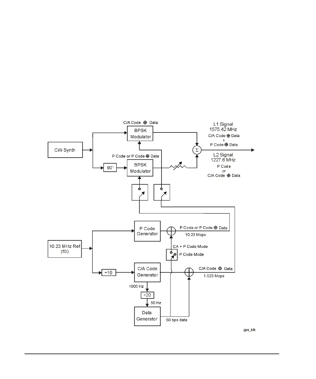
Figure 11-3 shows how the GPS signal is generated within the ESG. Notice that the C/A code modulates the
L-band signal using the I axis of the I/Q modulator, and the P code modulates the L-band signal using the Q
axis. Select the data provided by the data generator using the
Data softkey or by choosing the TLM data
mode.
Figure 11-3 GPS Signal Generation Diagram