Chapter 16 453
W-CDMA Uplink Digital Modulation for Receiver Test
Understanding the PRACH
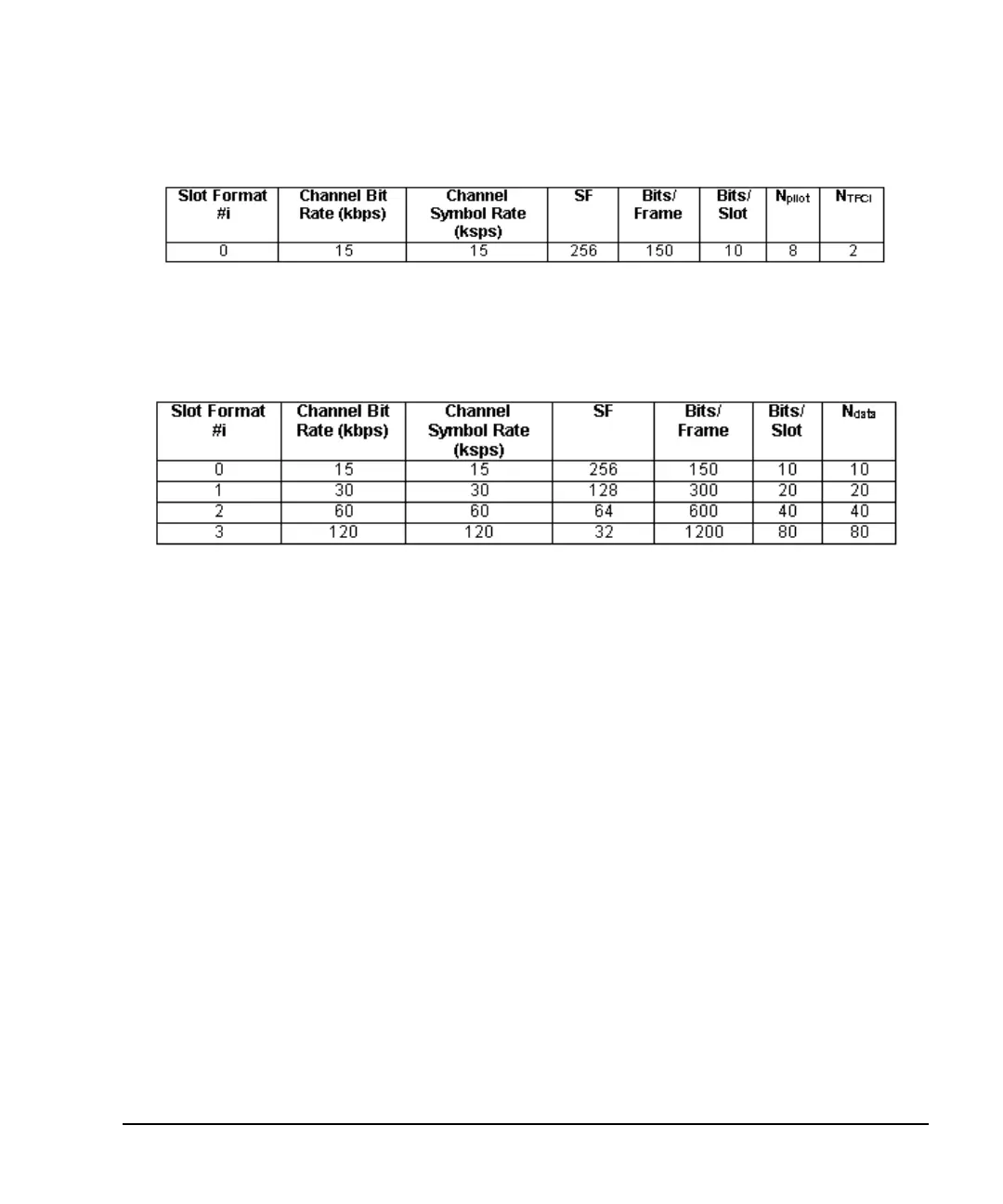
Figure 16-5 Control Part Slot Format
Unlike the control part, the data part has multiple slot formats that enable it to transmit at different data rates.
This is shown in Figure 16-6.
Figure 16-6 Data Part Slot Format
Message Part Scrambling Codes
As stated in “Scrambling Codes” on page 451, the same code is used for both the message part and the
preamble. However the starting chip for the message part is shifted by 4096 chips from the preamble code.
The message part contains 38400 scrambling chips and they are repeated every 10 ms (every radio frame).
So a 20 ms message part would have two repetitions of the same code.
Power Control
The PRACH power is controlled by setting the preamble and the message part power. The PRACH power is
determined by the component (preamble or message part) of the PRACH that has the highest power level. If
both components have the same power level, then both components individually equal the PRACH power
level. The message part power is comprised of the absolute powers for the control part and data part. A
PRACH power value can be entered that exceeds the current displayed carrier power and vice versa. But in
reality, the PRACH power equals the carrier power; it cannot exceed it. When a PRACH over power
condition occurs, the ESG will automatically adjust the PRACH power or the carrier power to keep them
within limits. In the multiple PRACH mode, the ESG maintains an 18.06 dB offset between the carrier
power and the PRACH power level. This is so the ESG can accommodate the additional power required
when more UEs (user equipment/mobiles) are utilized (see “Understanding the Power Offset Between the
Carrier and the Multiple PRACH” on page 477 for more information).