234 Chapter 7
Digital Signal Interface Module
Operating the N5102A Module in Output Mode
Operating the N5102A Module in Output Mode
This section shows how to set the parameters for the N5102A module using the signal generator UI in the
output direction. Each procedure contains a figure that shows the softkey menu structure for the interface
module function being performed.
Setting up the Signal Generator Baseband Data
The digital signal interface module receives data from a baseband source and outputs a digital IQ or digital
IF signal relative to the selected logic type. Because an ESG provides the baseband data, the first procedure
in operating the interface module is configuring the ESG using one of the real-time or ARB modulation
formats, or playing back a stored file using the Dual ARB player. For information on configuring the ESG,
refer to Chapter 4, “Basic Digital Operation,” on page 89.
1. Preset the signal generator.
2. Select the modulation format (TDMA, Custom, and so forth) and set the desired parameters.
3. Turn-on the modulation format.
Accessing the N5102A Module User Interface
Press Aux Fctn > N5102A Interface.
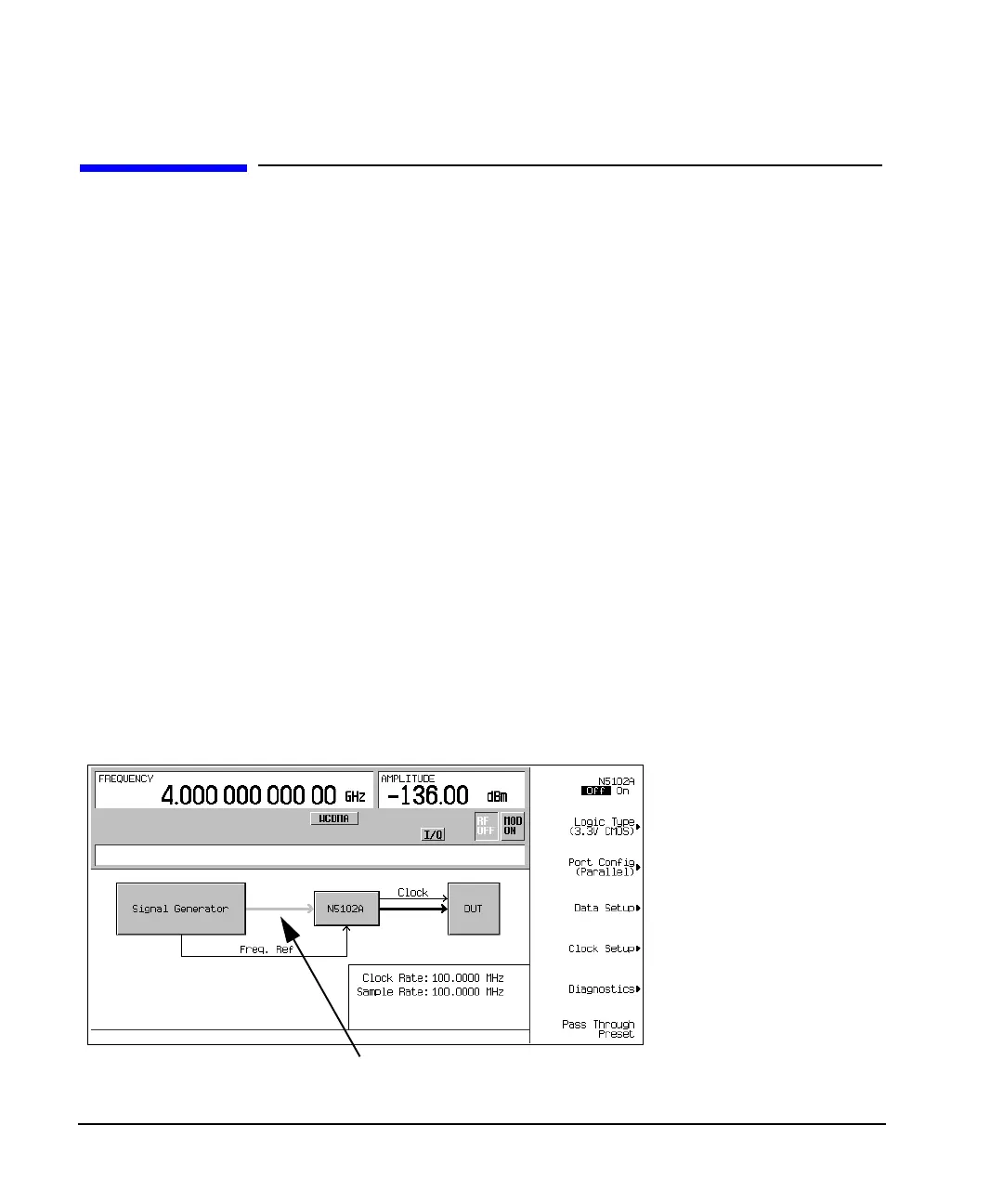
This accesses the UI (first-level softkey menu shown in Figure 7-9) that is used to configure the digital
signal interface module. Notice the graphic, in the ESG display, showing a setup where the N5102A module
is generating its own internal clock signal. This graphic changes to reflect the current clock source selection.
Figure 7-9 First-Level Softkey Menu
Line is grayed out until the N5102A module interface is turned on