142 Chapter 4
Basic Digital Operation
Using Waveform Markers
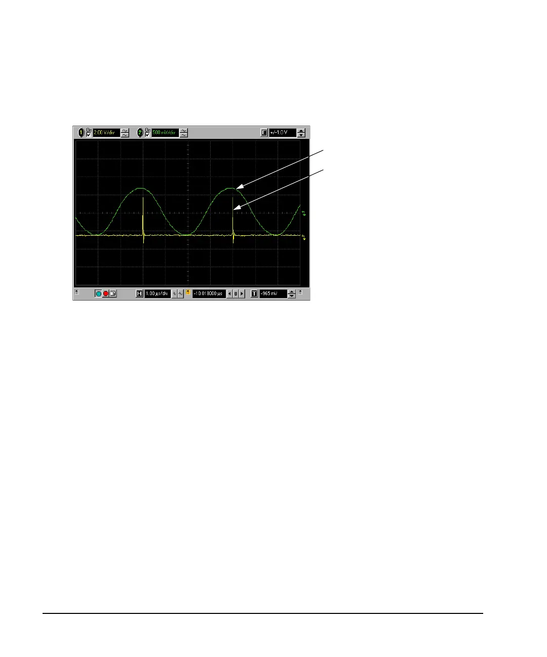
4. Connect the ESG’s rear-panel EVENT 1 output to the oscilloscope’s channel 2 input. When marker 1 is
present, the ESG outputs a signal on the EVENT 1 connector as shown in the following example.
Using the RF Blanking Marker Function
While you can set a marker function (described as Marker Routing on the softkey label) either before or after
setting the marker points (page 137), setting a marker function before you set marker points may change the
RF output. RF Blanking includes ALC hold (described on page 131, note Caution regarding unleveled
power). The signal generator blanks the RF output when the marker signal goes low.
1. Using the factory-supplied segment SINE_TEST_WFM, set Marker 1 across points 1−180 (page 137).
2. From the
Marker Utilities menu (page 134), assign RF Blanking to Marker 1:
RF Output
Marker pulse on the Event 1 signal.