Chapter 9 289
BERT
Bit Error Rate Tester–Option UN7
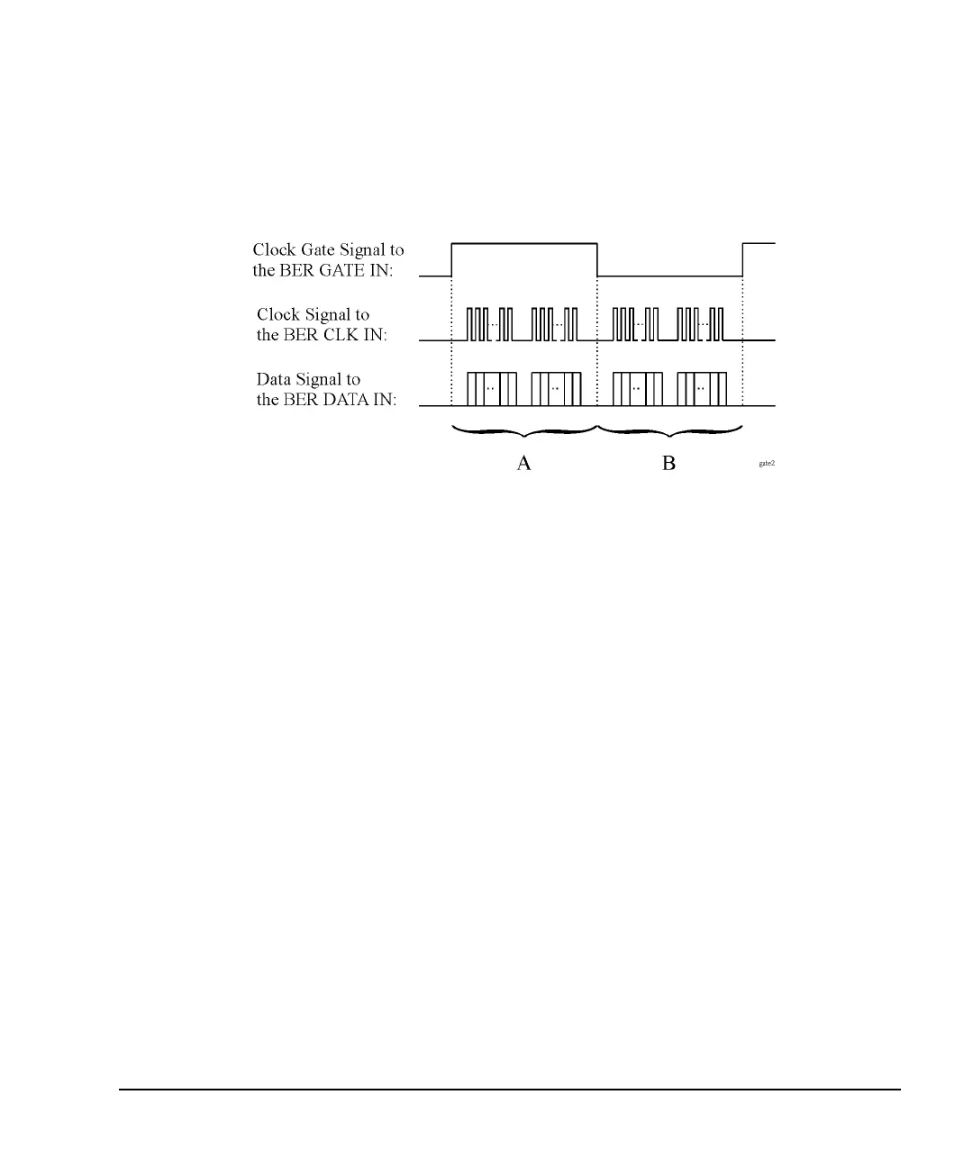
The following figure shows an example of the clock gate signal.
Figure 9-19
• When the
Clock Gate Off On softkey is set to Off:
The clock signal in both “A” and “B” parts is effective and no gate function is required. Therefore, the
bit error rate is measured using the clock and data signal in both “A” and “B” parts.
• When the
Clock Gate Off On softkey is set to On, and the Clock Gate Polarity Neg Pos softkey is set to Pos:
The clock signal in “A” part is effective. Therefore, the bit error rate is measured using the clock and
data signals in “A” part.
• When the
Clock Gate Off On softkey is set to On, and the Clock Gate Polarity Neg Pos softkey is set to Neg:
The clock signal in “B” part is effective. Therefore, the bit error rate is measured using the clock and
data signals in “B” part.
Clock/Gate Delay Function
This function enables you to restore the timing relationship between the clock/gate timing as it passes
through the unit under test (UUT) and the packet data.
The shifted clock signal is emitted from pin 20 of the AUX I/O rear panel connector. When you use the
clock delay function, the clock signal to the BER CLK IN connector is delayed by the clock delay function.
When you use the gate delay function with the clock gate function, the clock signal is gated by the gate
signal which is delayed by the gate delay function.
To see the signal flow using the clock and gate functions, refer to Figure 9-20.