376 Chapter 13
Custom Digital Modulation
Using the Arbitrary Waveform Generator
Modifying Carrier Power
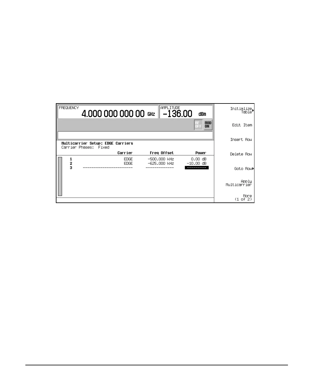
1. Highlight the Power value (0.00 dB) for the carrier in row 2.
2. Press
Edit Item > -10 > dB.
You now have a custom 2-carrier EDGE waveform with a carrier at a frequency offset of −625 kHz and
a power level of −10.00 dBm, as shown in the following figure.
Generating the Waveform
Press
Return > Digital Modulation Off On.
This generates a waveform with the custom multicarrier EDGE state created in the previous sections. The
display changes to Dig Mod Setup: Multicarrier (Modified). During waveform generation, the
DIGMOD and I/Q annunciators appear and the new custom multicarrier EDGE state is stored in volatile
memory. The waveform is now modulating the RF carrier.
For instructions on storing this custom multicarrier EDGE state to non-volatile memory, see “Storing a
Custom Multicarrier TDMA Digital Modulation State” on page 377.
Configuring the RF Output
1. Set the RF output frequency to 890.01 MHz.
2. Set the output amplitude to −10 dBm.
3. Press
RF On/Off.
The custom multicarrier EDGE signal is now available at the RF OUTPUT connector.