100
8331B–AVR–03/12
Atmel AVR XMEGA AU
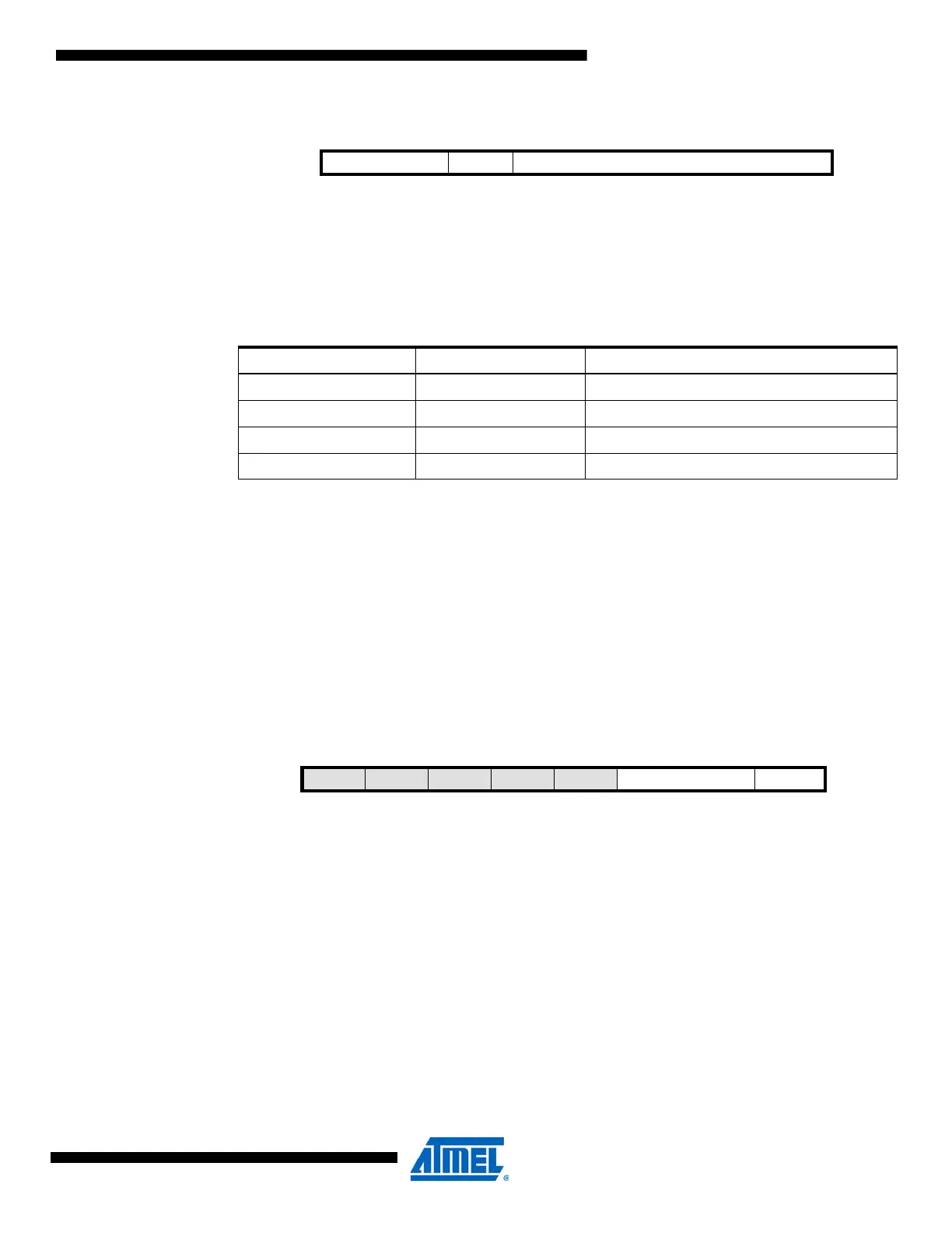
7.10.6 PLLCTRL – PLL Control register
• Bit 7:6 – PLLSRC[1:0]: Clock Source
The PLLSRC bits select the input source for the PLL according to Table 7-9 on page 100.
Notes: 1. The 32.768kHz TOSC cannot be selected as the source for the PLL. An external clock must be
a minimum 0.4MHz to be used as the source clock.
• Bit 5 – PLLDIV: PLL Divided Output Enable
Setting this bit will divide the output from the PLL by 2.
• Bit 4:0 – PLLFAC[4:0]: Multiplication Factor
These bits select the multiplication factor for the PLL. The multiplication factor can be in the
range of from 1x to 31x.
7.10.7 DFLLCTRL – DFLL Control register
• Bit 7:3 – Reserved
These bits are unused and reserved for future use. For compatibility with future devices, always
write these bits to zero when this register is written.
• Bit 2:1 – RC32MCREF[1:0]: 32MHz Oscillator Calibration Reference
These bits are used to select the calibration source for the 32MHz DFLL according to the Table
7-10 on page 101. These bits will select only which calibration source to use for the DFLL. In
addition, the actual clock source that is selected must enabled and configured for the calibration
to function.
Bit 76543210
+0x05 PLLSRC[1:0] PLLDIV PLLFAC[4:0] PLLCTRL
Read/Write R/W R/W R/W R/W R/W R/W R/W R/W
Initial Value00000000
Table 7-9. PLL Clock Source
PLLSRC[1:0] Group Configuration PLL Input Source
00 RC2M 2MHz internal oscillator
01 — Reserved
10 RC32M 32MHz internal oscillator
11 XOSC External clock source
(1)
Bit 765432 1 0
+0x06 – – – – – RC32MCREF[1:0] RC2MCREF DFLLCTRL
Read/Write R R R R R R/W R/W R/W
Initial Value 0 0 0 0 0 0 0 0
 Loading...


