3-52
Confidential
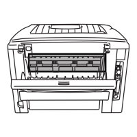
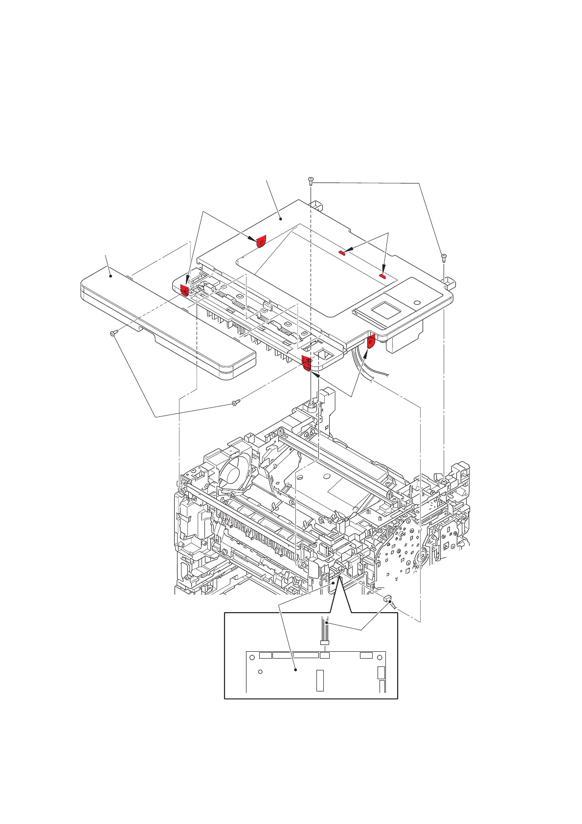
9.10.2 Top cover ASSY
(1) Remove the MX cover.
(2) Disconnect the stack sensor harness from the main PCB ASSY, and release it from the
securing fixtures.
(3) Remove the four taptite bind B M4x12 screws.
(4) Release the hook A first, and then release the hook B. Remove the top cover ASSY.
Fig. 3-36
Harness routing: Refer to “1. Left side of the machine (Touch panel models)”.
Top cover ASSY
MX cover
Taptite bind B M4x12 (black)
Taptite bind B M4x12
Hooks B
Hooks B
Hooks A
Stack sensor
harness
Main PCB ASSY
 Loading...