3-90
Confidential
9.28 Fuser drive gear 39
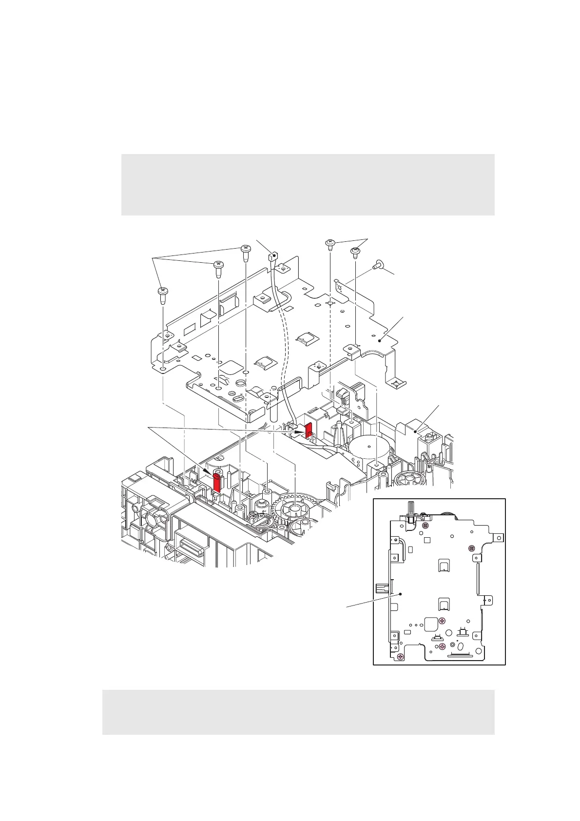
(1) Remove the three taptite bind B M4x12 screws, taptite cup S M3x8 SR screw (A), and
two taptite cup S M3x8 SR screws (B). Release the two hooks to remove the main PCB
shield calking ASSY from the main frame L ASSY. Pull out the eject motor harness from
the hole of the main PCB shield calking ASSY.
Fig. 3-79
Note:
• Screw A is not equipped for models with 250-sheet T1.
• Do not allow the metallic gear shaft of the main PCB shield calking ASSY to face
down. Failure to observe this may cause the steel plate to bend.
Assembling Note:
• When securing the main PCB shield calking ASSY with screws, tighten the screws in
the sequence of the numbers engraved on the main PCB shield calking ASSY.
Taptite cup S M3x8 SR (B)
Taptite bind B
M4x12
Main PCB shield calking ASSY
Main frame L ASSY
Hooks
Eject motor harness
2
4
1
3
Main PCB shield calking ASSY
5
Taptite cup S M3x8 SR (A)
 Loading...