2-227
CHAPTER 2 NEW FUNCTIONS
COPYRIGHT
©
2001 CANON INC. 2000 2000 2000 2000 CANON CLC5000 REV.0 JAN. 2001
Buffer pass
power supply
Cover switch (SW1)
Buffer pass driver PCB
+24VR
+24VR
+24VR
+24VR
+24VR
+24VR
+24VR
+5V
+5V
+5V
+5V
+5V
+5V
+5V
+5V
J205B-1
J205B-2
J302-1
J302-2
J302-3
J302-4
J530-2
J530-1
J532-1
J532-2
J532-3
J532-4
REMON
J303-2
+24V
J301-1,3
Cover switch
24V/5V
DC/DC converter
Leakage
breaker
Noise
filter
outlet
To sorter
Reversal jam sensor 2 (PS2)
Delivery paper sensor (PS3)
Upper phase sensor 1 (PS4)
Upper phase sensor 2 (PS5)
Lower phase sensor 1 (PS6)
Lower phase sensor 2 (PS7)
Inlet paper sensor (PS8)
Reversal motor (M2)
Buffer pass motor (M1, M3)
Flapper solenoid (SL1)
Downward curl removing
solenoid 1 (SL3)
Downward curl removing
solenoid 2 (SL4)
Upward curl removing
solenoid 1 (SL5)
Upward curl removing
solenoid 2 (SL6)
Reversal timing sensor 1 (PS1)
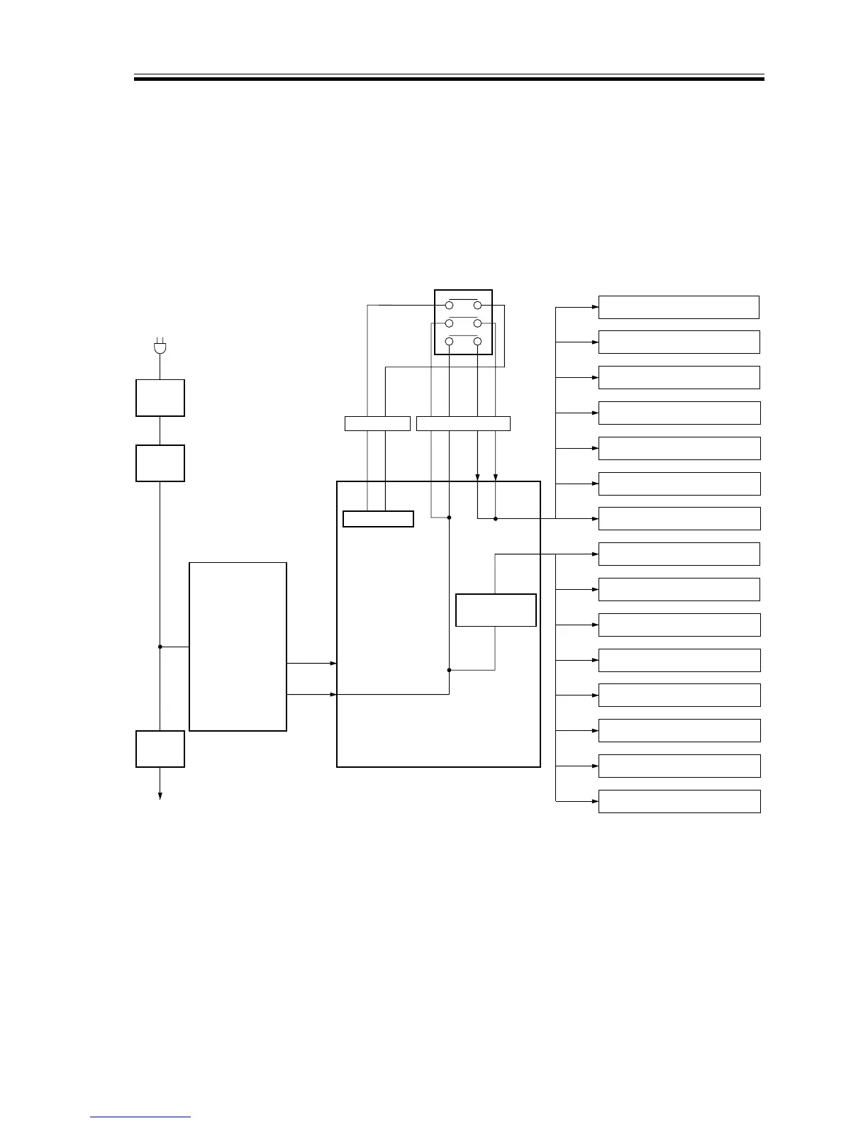
9.6 Power Supply
9.6.1 Outline
The following diagram shows how power is distributed. The buffer pass unit is supplied
with +5V and +24V power by the buffer pass power supply. +24 V is supplied by way of the
cover switch (SW1) to the loads; it will be cut off when the front cover of the buffer pass
unit is opened and, as a result, the cover switch turns off.
F02-906-01