COPYRIGHT
©
2001 CANON INC. 2000 2000 2000 2000 CANON CLC5000 REV.0 JAN. 2001
CHAPTER 5 TROUBLESHOOTING IMAGE FAULTS/MALFUNCTIONS
5-52
2.9 Fixing Assembly-Related Parts
2.9.1 Points to Note When Replacing the Fixing Heater
• Do not touch the surface of the heater.
REF.
Neither fixing heater (upper/
lower) has any specific front/
rear orientation.
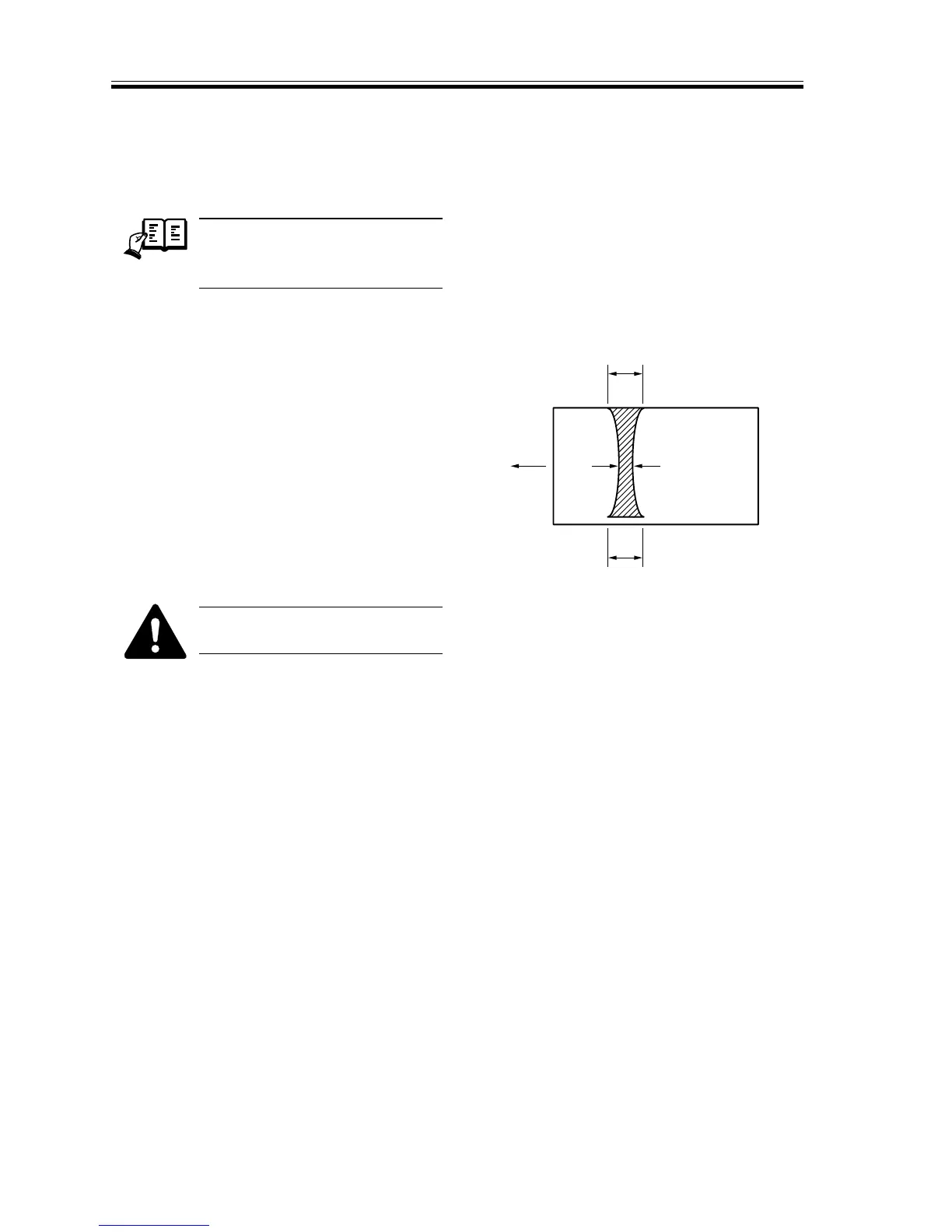
2.9.2 Adjusting the Nip (fixing pressure adjusting nut)
• Check to make sure that the nip
width is as indicated in T04-209-01.
If not, turn the adjusting screw to adjust.
F05-209-01
a and c represent points 10 to 15
mm from the edges.
Dimension Measurements*
a 7.5 ±0.5 mm
| b-c | 0.5 mm or less
b-a 0.5 mm or less
c-a 0.5 mm or less
* Taken when the upper and lower rollers
are sufficiently heated.
T05-209-01
Measuring the Nip Width
If the fixing rollers are cool, wait until
the standby period is over, wait an addi-
tional 15 min, and make 30 copies before
taking measurements.
b
c
a
Center of
copy paper
A3
Feeding
direction