COPYRIGHT
©
2001 CANON INC. 2000 2000 2000 2000 CANON CLC5000 REV.0 JAN. 2001
CHAPTER 5 TROUBLESHOOTING IMAGE FAULTS/MALFUNCTIONS
5-43
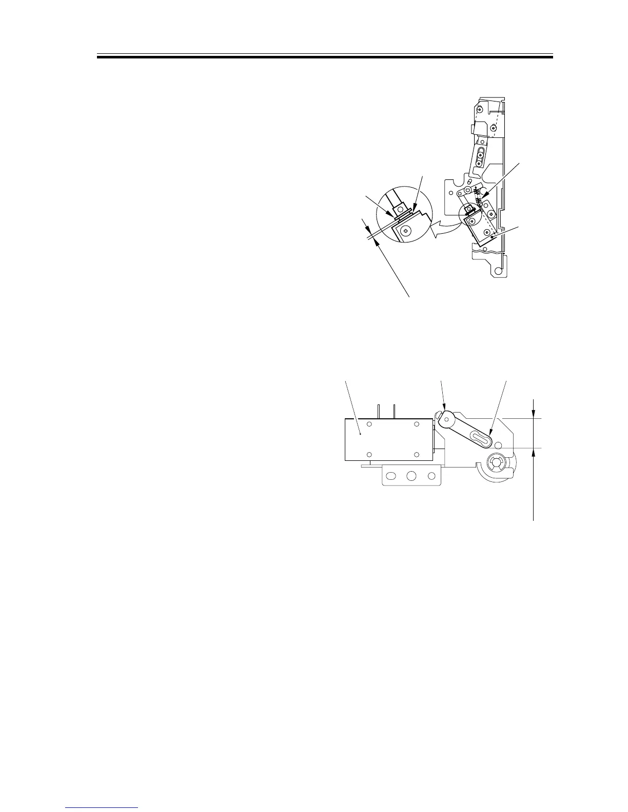
2.7.19 Adjusting the Position of the Separation Claw Solenoid (SL15)
1) Place the delivery assembly upright.
2) Fix the solenoid in place where the dis-
tance between the E-ring [3] and the
resin washer [4] is 3.5 ±0.5 mm when
the plunger of the solenoid [1] is pulled
by the spring [2].
F05-207-21
2.7.20 Adjusting the Position of the Upper Fixing Web Take-Up Solenoid
(SL3)
1) Keep the delivery assembly upright.
2) Fix the solenoid in place so that the verti-
cal distance between the top end of the
solenoid shaft [2] and the top end of the
solenoid lever [3] is 16.3 ±0.2 mm when
the plunger of the solenoid [1] is pushed.
F05-207-22
2.7.21 When Replacing the Registration Roller Unit
You must make adjustments as follows
whenever you have replaced the registration
roller unit:
1) Replace the registration roller unit.
2) Make several copies of the Test Chart,
and check the leading edge margin, left/
right margin, and for skew movement.
3) If the leading edge margin is not as
specified, make adjustments once again.
(For standards and method, See Chapter
5>2.1 Image-Related Parts)
4) If skew movement is noted, make ad-
justments as instructed in the section
that follows.
[3]
[4]
3.5±0.5mm
[2]
[1]
20.5±0.2mm
[1] [2] [3]
 Loading...


