2-208
COPYRIGHT
©
2001 CANON INC. 2000 2000 2000 2000 CANON CLC5000 REV.0 JAN. 2001
CHAPTER 2 NEW FUNCTIONS
J203 J202
J201
Sensor Solenoid
Reversal timing sensor
Reversal jam sensor
Delivery sensor
Upward curl phase
sensor 1
Upward curl phase
sensor 2
Downward curl phase
sensor 1
Downward curl phase
sensor 2
Inlet paper sensor
•
•
•
•
•
•
•
•
•
•
•
•
•
•
•
•
•
•
•
•
Flapper solenoid
Downward curl removing
solenoid 1
Downward curl removing
solenoid 2
Upward curl removing
solenoid 1
Upward curl removing
solenoid 2
Sorter
Buffer pass driver PCB
Control
signal
Copier
Serial
signal
Buffer output motor
Reversal motor
Buffer input motor
Cooling fan 1
Cooling fan 2
Cooling fan 3
Cooling fan 4
Motor
Fan
motor
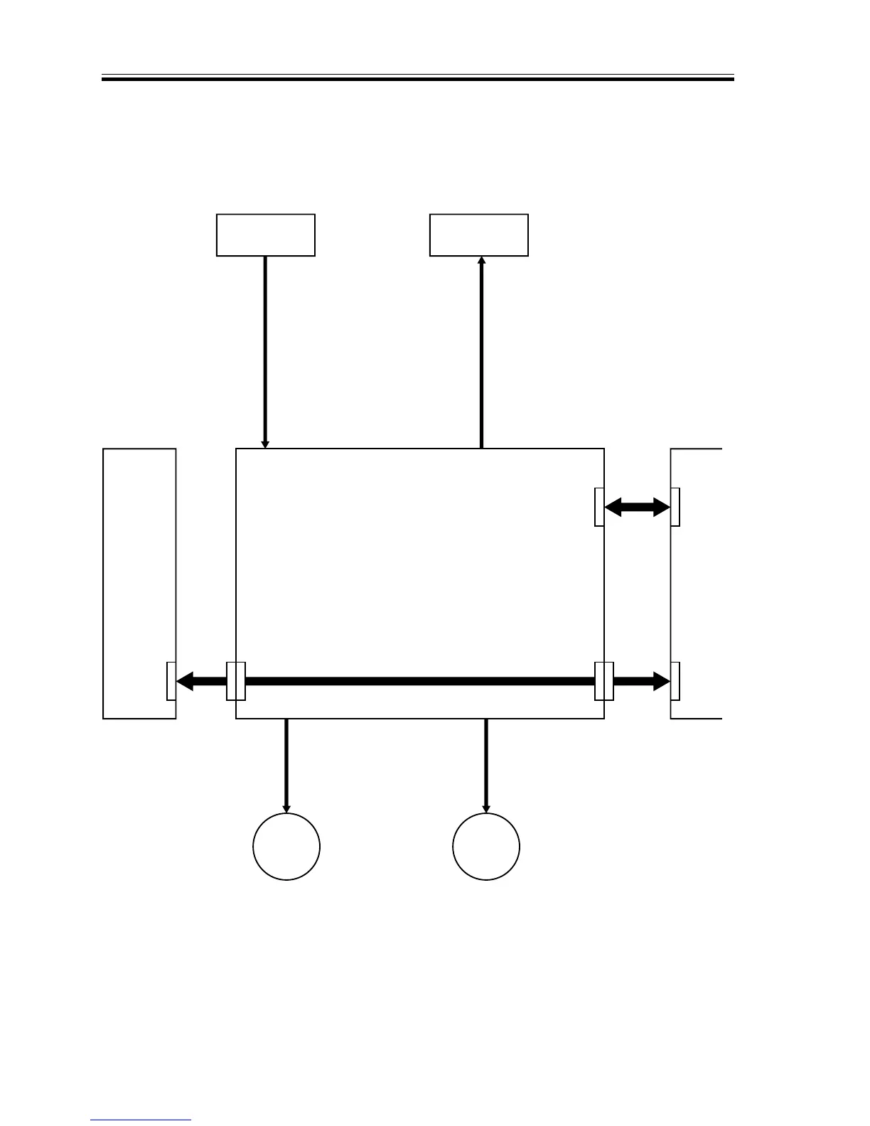
9.1.1 Outline of the Electrical Circuitry
The electric mechanisms of the machine are controlled by its host copier (i.e., the ma-
chine is not equipped with controller PCB of its own). The signals from the copier are re-
ceived by the buffer pass unit drive PCB to drive the motors, solenoids, and clutches.
F02-901-02