2-169
CHAPTER 2 NEW FUNCTIONS
COPYRIGHT
©
2001 CANON INC. 2000 2000 2000 2000 CANON CLC5000 REV.0 JAN. 2001
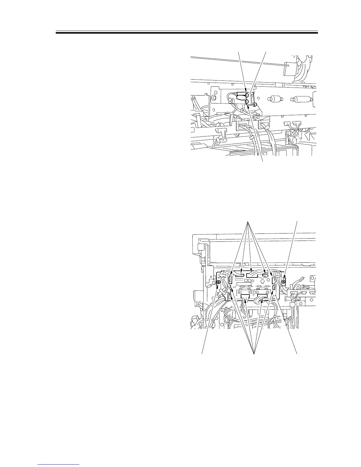
7.6.2 Switches
a. Removing the Rear Cover Switch
1) Remove the rear cover (2).
2) Remove the laser scanner motor cooling
fan unit.
3) Remove the two screws [1], and detach
the rear cover switch [2].
[1] [2]
[1]
[2]
[2]
[1]
[1]
[3]
F02-706-22
7.6.3 PCBs
a. Removing the Multifeeder PCB
1) Remove the rear cover (2).
2) Remove the two screws [1], and discon-
nect the 10 connectors [2]; then, detach
the multifeeder PCB [3].
F02-706-23