CAPINTEC, INC. CRC
®
-25R
Note: To avoid damage, do not over-tighten the screws on the Cable connectors.
The screws should be finger-tightened only!
3. Attach the Power Cable to the receptacle on the Power Module located on the back
of the Readout Unit.
Note: Do not place the Readout unit against a wall or other object so that the power
cord can be detached from the back of the Readout unit.
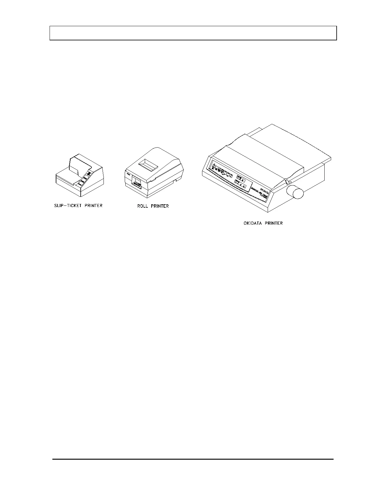
Figure 4-2 Printers
4. If the optional printer is an RS-232 (serial) version, attach the printer cable (one end
has a 9 pin “D” connector, the other end has a 25 pin “D” connector) to the connector
at the rear of the CRC
®
-25R Readout marked “PRINTER”. Attach the other end to the
printer.
Note: To avoid damage, do not over-tighten the screws on the Cable connectors.
The screws should be finger-tightened only!
Note: Do not attach the printer cable to the “RS232” connector.
If the optional printer is a USB version, attach the printer cable to the connector on
the rear of the CRC
®
-25R Readout marked “PRINTER”. Attach the other end to the
printer.
Note: Do not attach the printer cable to the “PC” connector.
5. For each printer type, verify that the correct paper is installed.
Note: The Slip-Ticket printer paper is manually inserted at the time of printing.
March 15 SYSTEM SETUP 4 - 3