Performing a Manual Isolation Test
The isolation between BDA Donor Antenna and In-Building Services Antenna determines the maximum
downlink gain or uplink gain. It is required that the Gain (Set in the BDA) <= Isolation -20
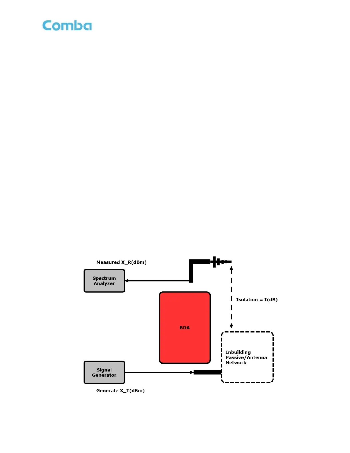
Follow the instructions below for the recommended isolation test setup:
1. Disconnect the Donor Antenna feedline cable from the DT Port of BDA and the Service Antenna
feedline cable from the MT port of the BDA.
2. Connect a Signal Generator to the Service Antenna feedline cable. It’s not recommended for the
Signal Generator to be used on the DT side, as it could cause interference with outdoor radio
networks.
3. Connect a Spectrum Analyzer to the Donor Antenna feedline cable.
4. If using a CW tone for the test, pick a frequency to use for the test. Before the CW turns on, make
sure there is no other signal on this frequency seen on the Spectrum Analyzer. After this is set up,
turn on the CW, and measure the level on the Spectrum Analyzer. The output level from Signal
Generator is represented by X_T(dBm) and the received power from the Spectrum Analyzer is
represented as X_R(dBm). The isolation is calculated as:
I(dB) = X_T – X_R
For example:
X_T = 10dBm, X_R= -95dBm
I = 10 – (-95) = 105dB
It is recommended to generate a minimum of 3 frequencies at low, mid, high at each passband for the test,
including the uplink band. For example: 769MHz, 772MHz, 775MHz, 799MHz, 807MHz, 816MHz, 851MHz,
856MHz, 861MHz.
Note: Using a tracking Generator can observe the entire passband and provides the most accurate
value of Isolation. It is preferred. The isolation can be calculated from the <output power – received
power>
Figure 127: Commissioning Tools – Isolation Check - Performing a Manual Isolation test
 Loading...