UMN:CLI User Manual
V8102
38
Illustrations
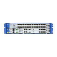
Fig. 2.1 Front View of the V8102 ................................................................................ 45
Fig. 5.1 Slot Assignment of V8102 ............................................................................. 86
Fig. 5.2 Structure of IPv6 Header ............................................................................... 98
Fig. 6.1 Ping Test for Network Status ....................................................................... 130
Fig. 6.2 IP Source Routing ....................................................................................... 131
Fig. 7.1 OAM Deployment Scenario ......................................................................... 179
Fig. 7.2 CFM and Y.1731 OAM for end-to-end visibility ........................................... 184
Fig. 7.3 Shared MEG Levels .................................................................................... 185
Fig. 7.4 Ring Protection in case of Link Failure ........................................................ 206
Fig. 7.5 Ring Recovery Procedure ........................................................................... 206
Fig. 7.6 Uplink Redundancy Deployment Scenario .................................................. 214
Fig. 7.7 NetBIOS Filtering ........................................................................................ 220
Fig. 7.8 Port Mirroring ............................................................................................... 222
Fig. 7.9 ICMP Message Structure ............................................................................ 229
Fig. 8.1 Proxy ARP ................................................................................................... 277
Fig. 8.2 Process of 802.1x Authentication ................................................................ 300
Fig. 8.3 Multiple Authentication Servers ................................................................... 301
Fig. 9.1 Port-based VLAN ........................................................................................ 308
Fig. 9.2 Example of QinQ Configuration................................................................... 314
Fig. 9.3 QinQ Frame ................................................................................................. 314
Fig. 9.4 Link Aggregation .......................................................................................... 323
Fig. 9.5 Procedure of QoS operation ........................................................................ 330
Fig. 9.6 Structure of Rule .......................................................................................... 331
Fig. 9.7 Token Bucket Meter ..................................................................................... 340
Fig. 9.8 Behavior of srTCM (1) ................................................................................. 341
Fig. 9.9 Behavior of srTCM (2) ................................................................................. 342
Fig. 9.10 Behavior of srTCM (3) ................................................................................. 342
Fig. 9.11 Behavior of trTCM (1) .................................................................................. 343
Fig. 9.12 Behavior of trTCM (2) .................................................................................. 344
Fig. 9.13 Behavior of trTCM (3) .................................................................................. 344
Fig. 9.14 Strict Priority Queuing .................................................................................. 356
Fig. 9.15 Deficit Round Robin .................................................................................... 357
Fig. 9.16 Weighted Round Robin ............................................................................... 357
Fig. 9.17 WRED Packet Drop Probability ................................................................... 362
Fig. 9.18 Example of Loop ......................................................................................... 363
Fig. 9.19 Principle of Spanning Tree Protocol ............................................................ 363
Fig. 9.20 Root Switch ................................................................................................. 364
Fig. 9.21 Designated Switch ....................................................................................... 365
Fig. 9.22 Port Priority .................................................................................................. 366
Fig. 9.23 Port States ................................................................................................... 366
Fig. 9.24 Alternate Port and Backup port ................................................................... 368
Fig. 9.25 Example of Receiving Low BPDU ............................................................... 369
Fig. 9.26 Convergence of 802.1d Network ................................................................. 370
Fig. 9.27 Network Convergence of 802.1w (1) ........................................................... 370
Fig. 9.28 Network Convergence of 802.1w (2) ........................................................... 371
Fig. 9.29 Network Convergece of 802.1w (3) ............................................................. 371
Fig. 9.30 Compatibility with 802.1d (1) ....................................................................... 372
Fig. 9.31 Compatibility with 802.1d (2) ....................................................................... 372
Fig. 9.32 CST and IST of MSTP (1) ........................................................................... 373


 To Next Page