Dimension* Measurement description
U Diameter of the coupling.
V Center of the inboard foot on the left machine to the center of the
coupling.
*Measure to the nearest 1/8 inch (3 mm).
b. Use the left or right arrow keys to modify where the target dial indicator readings
are taken and press F2 Change Sensor Location.
The dial indicator location determines the direction (sign) of the RIM TIR (total
indicator runout). For example, if the left machine is to be set 3 mils high, the dial
indicator location is on the left machine shaft, and the top target reading is 0.0,
then the bottom reading would be -6.0 mils. With the same conditions and the
dial indicator on the right machine shaft, the bottom reading would be +6.0 mils.
c.
Enter the target face and rim dial indicator readings and press Enter.
This displays the Growth At Feet screen showing the calculated vertical and
horizontal thermal growth at each machine foot.
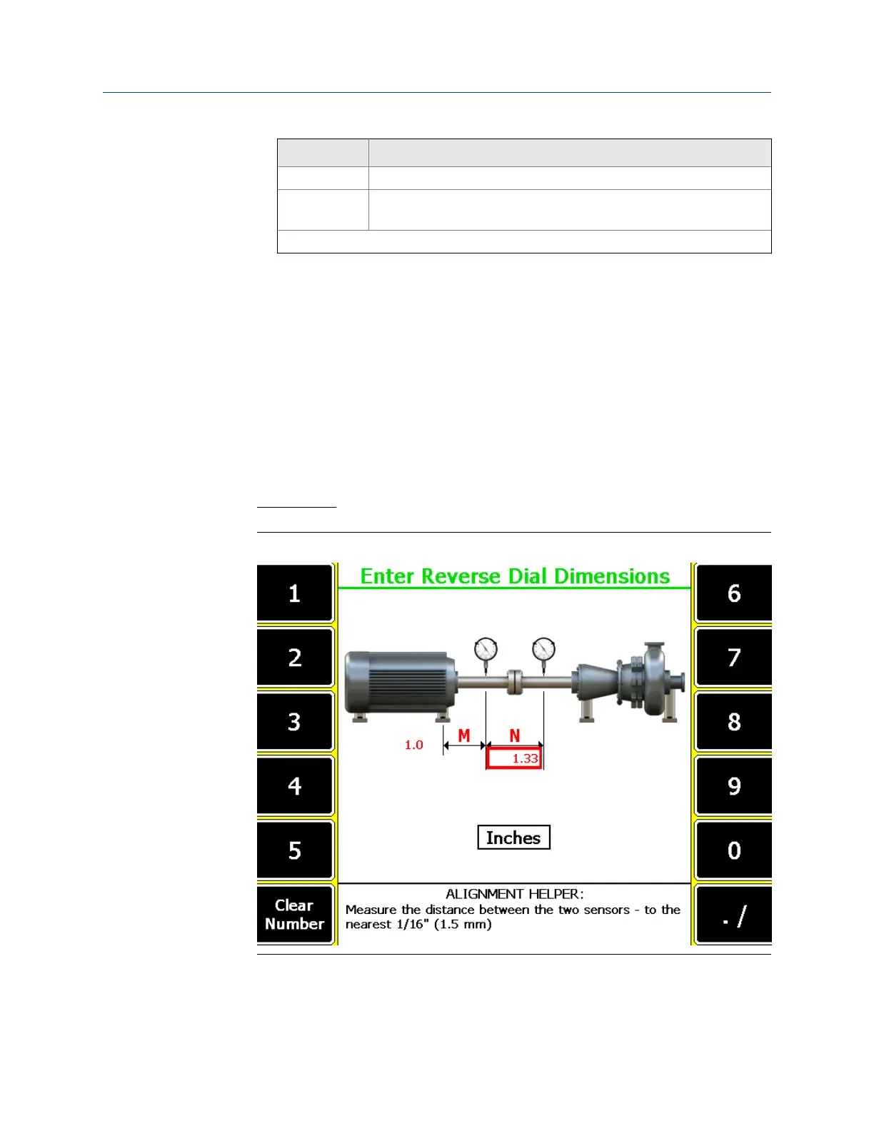
Reverse Dial
Reverse dialFigure 7-22:
a. Enter dimensions for the dial indicators and their relationship with respect to the
machine feet locations as defined in the Enter Dimensions screen and press Enter.
Advanced Laser Alignment
206 MHM-97432 Rev 7
 Loading...


