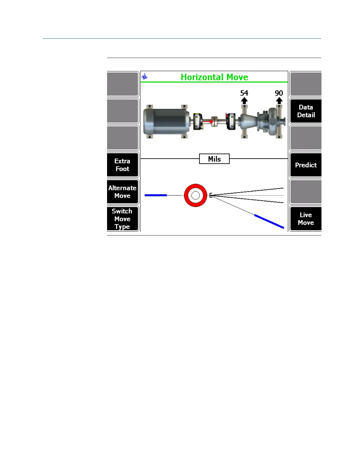
Horizontal machine moveFigure 7-32:
For horizontal machine moves, if the required movement is positive, the amount of
movement is shown below the machine at the appropriate foot with a down arrow.
If the required movement is negative, the amount of movement is shown above the
machine at the appropriate foot with an up arrow.
The bottom half of the analyzer screen shows a bull's-eye target and a shaft
centerline plot representing the alignment condition of the machine. The shaft
centerline plot includes a "V" shape indicating the acceptable angular tolerance on
the machine as well as a bracket at the base of the "V" showing the acceptable offset
misalignment at the coupling.
The bull's-eye target compares the total misalignment to the target tolerance. Each
circle in the bull's-eye target has a different meaning: red—more than two times the
tolerance, yellow—between one and two times the tolerance, green—within
acceptable tolerance, green with a star—within excellent tolerance.
Optionally, you can do the following:
a.
Press F4 Extra Foot to calculate the vertical and horizontal machine moves for up
to four machine foot locations in addition to those defined for the job.
See Section 7.5.8 for more information on calculating moves for extra feet.
b. Press F5 Alternate Move to switch between the alternate pairs of feet where the
machine moves can be made.
If all dimensions are entered, up to six alternate moves are available.
Advanced Laser Alignment
220 MHM-97432 Rev 7
 Loading...


