031914 2-1
INTRODUCTION
The following is a brief description of the key Slicer
components as they relate to the “Theory of
Operation.” This section is intended to give the
machine user a better understanding of the Slicer
operation.
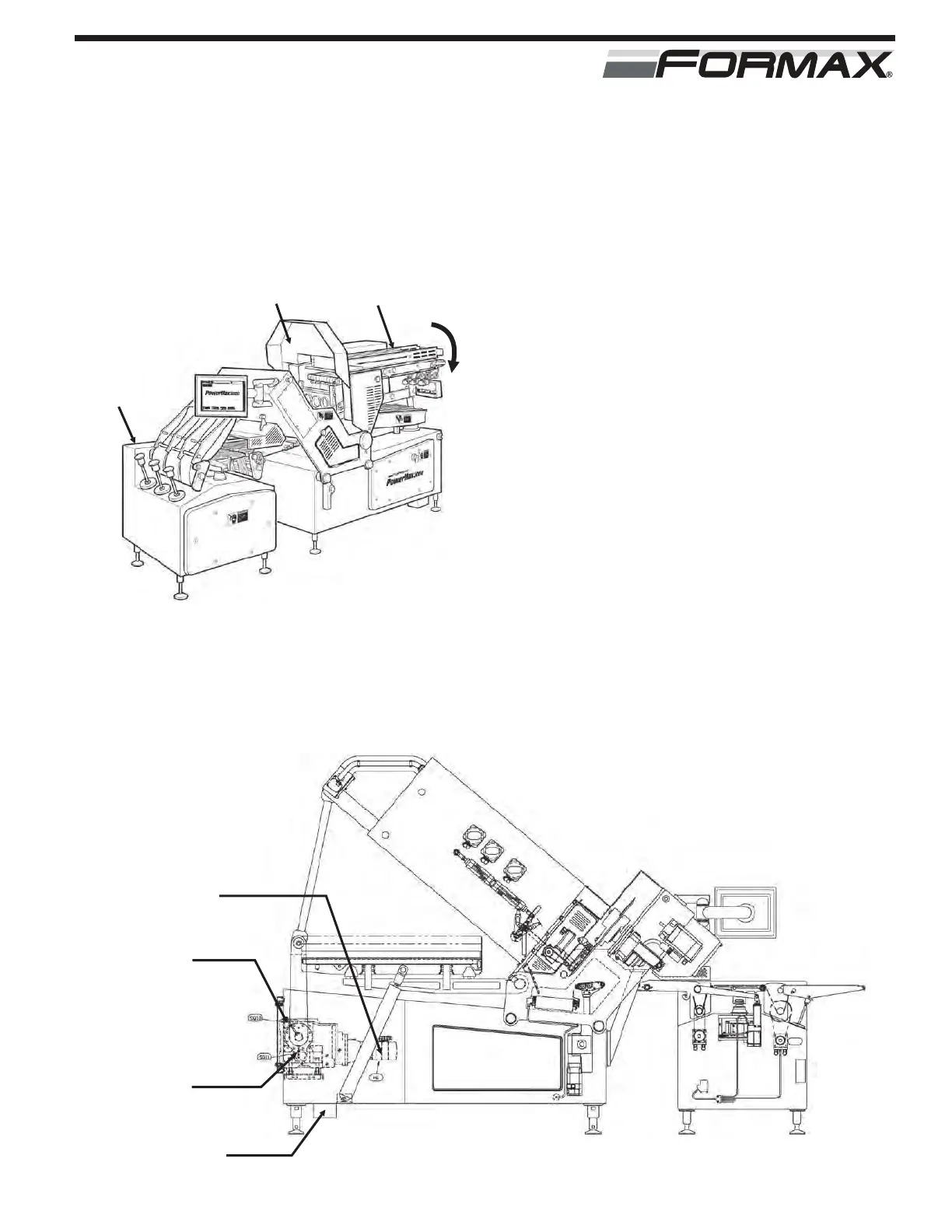
CLEAN-UP POSITION: The Slicer must be put in
the “Clean-up” position for sanitation and assembly
purposes. The Infeed Structure lowers to the “down”
position for access to the upper Infeed Conveyors,
Shear Bar, Knife and Counterweight. (Illustration 1)
INFEED STRUCTURE LIFT: The “Infeed Structure”
is raised and lowered by the M6 Servo Motor. The
U4 Servo Drive controls the M6 Servo Motor.
(Illustration 2) The SQ10 Proximity Switch signals
the Computer when the Infeed Structure is in the
“Up” position. The SQ11 Proximity Switch signals
the Computer when the Infeed Structure is in the
“Down” position. The HA1 “Safety Horn” will sound
an alarm signal as the Infeed Structure is raised or
lowered.
KNIFE COVER: The Knife Cover raises and lowers
with the Infeed Structure. (Illustration 1)
THEORY OF OPERATION
ILLUSTRATION 2
M6
SERVO MOTOR
SQ10
PROXIMITY
SWITCH
SQ11
PROXIMITY
SWITCH
HA1
“SAFETY HORN”
ILLUSTRATION 1
INFEED
STRUCTURE
KNIFE
COVER
SCALE
CABINET
“CLEAN-UP”
POSITION
 Loading...