M3-4 031914
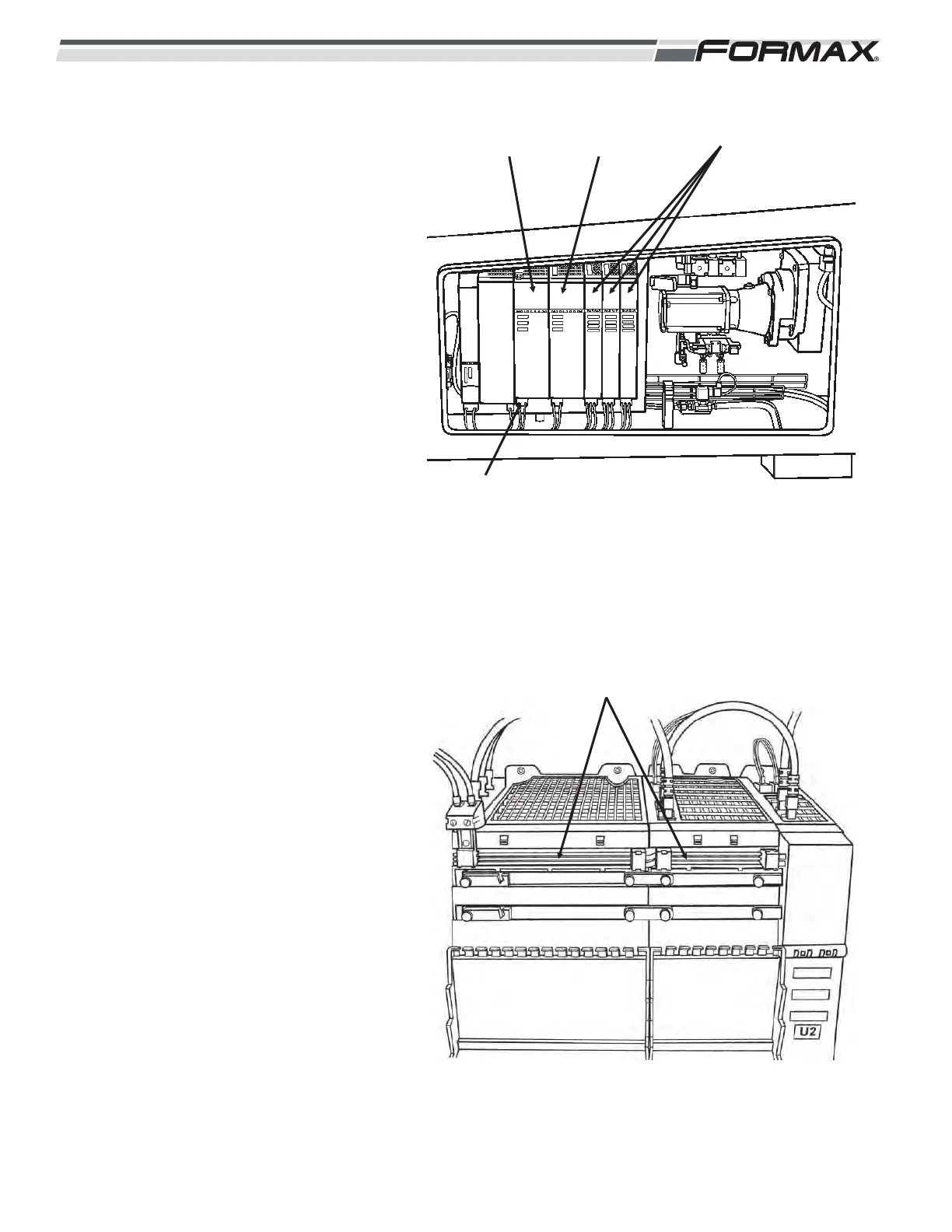
ACTIVE LINE MODULE: The “U3” Active
Line Module takes a 3 phase AC supply
voltage and rectifies it to approximately
650 VDC. (Illustration 7) The 650 VDC is
sent to each of the Servo Drives on the DC
Bus Bars running across the front of the
Servo Drives and is sent on a power cable
to the F1 and F2 fuses to the DC Bus Bars
on the U10, U11 and U12 Servo Drives.
(Illustration 8) The Servo Drives use this
voltage to operate and control the Servo
Motors. The Active Line Module receives
an external 24 VDC Control Voltage and
transfers this voltage to all of the Servo
Drives. Some Servo Motor applications will
actually generate DC voltage while running
and stopping. The Active Line Module
takes any generated or excess DC voltage
and converts it back to a 3 phase AC
waveform. After synchronizing the
waveform to the incoming power, the
regenerated AC voltage is returned to the
AC Supply Voltage. The Active Line
Controller also absorbs the excess voltage
generated when stopping a motor quickly.
SERVO DRIVE MODULES
The U4 Head Servo Drive Module controls
the Knife Servo Motor. All of the other
Servo Drives, “U5” through “U12,” control 2
Servo Motors. The Motion Control Modules
sends “speed” and “directional” command
signals to each Servo Drive to tell the
Servo Drive how fast and in what direction
to run each the Servo Motors. The Servo
Drives use the 650 VDC supplied by the
DC Bus to create a 3 phase AC voltage
and frequency to run and control the Servo
Motors. The Motion Control Modules use
the Resolver Feedback signals generated
by the Servo Motors to monitor and control
the Servo Motor. If a Servo Drive or Servo
Motor generates a “Fault,” a signal is sent
through the Profibus to the Computer and
a “Fault” message will display on the
Touchscreen.
ILLUSTRATION 7
U3
ACTIVE LINE
MODULE
U4
HEAD SERVO
DRIVE
U5 THROUGH U7
SERVO DRIVE MODULES
3-PHASE AC SUPPLY VOLTAGE
ILLUSTRATION 8
DC BUS BARS