031914 M4-17
IMPORTANT!
This section explains the electrical and electronic
sub-systems that make up the Slicer Control System. Refer
to the Electrical Schematic for more information as you
review this section.
ELECTRICAL OVERVIEW (3-PHASE AC SUPPLY
VOLTAGE)
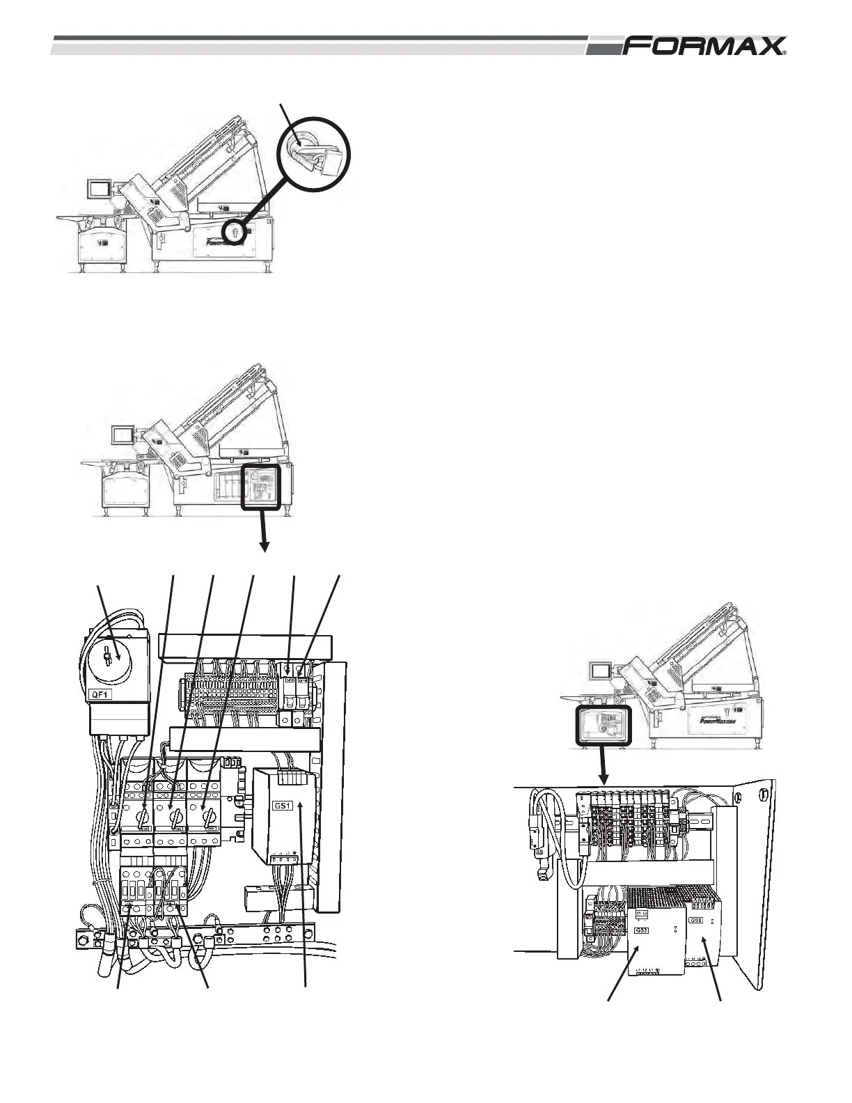
1. QF1 Circuit Breaker is a Disconnecting Device located on
the side of the machine that is used as a “Lockout/Tagout
Switch.” (Illustration 32) The QF1 Circuit Breaker
transfers the Plant Supply Voltage to the rest of the
machine components.
2. The 3-Phase AC Supply Voltage is sent to the Servo
Drives and the QM Circuit Controllers. (Illustration 33)
Refer to the Motion Control/Servo Drive section for more
information on the Motion Control/Servo Drive operation.
3. The QM Circuit Controllers are hand operated “On/Off”
switches with thermal overload protection. When in the
“On” position, the Circuit Controllers transfer the 3-phase
AC Supply Voltage to the KM Contactors. When
energized the KM Contactors transfer voltage to the
3-phase AC Debris Conveyor, the GS1, GS2, and GS3
Power Supplies and the optional Knife Heater.
(Illustration 34)
MAIN POWER HANDLE WITH LOCKOUT DEVICE
ILLUSTRATION 32
GS2 POWER SUPPLYGS3 POWER SUPPLY
ILLUSTRATION 34
ILLUSTRATION 33
QF1
BREAKER
QF9
KM2
CONTACTOR
QF10
GS1
POWER
SUPPLY
QM2 QM3 QM4
KM3
CONTACTOR