030712 M3-11
U3 ACTIVE LINE MODULE: ELECTRICAL
OVERVIEW
The “U3” Active Line Module takes a 3 phase AC
supply voltage and rectifies it to approximately 650
VDC. (Illustration 17) The 650 VDC is sent to each of
the Servo Drives on the DC Bus Bars located on the
front of the Drives. The DC Voltage is brought to the
U12 Servo Drive in the upper housing. It then travels
down the DC Bus Bars to the U11 and U10 Servo
Drives. (Illustration 18) The Servo Drives use this
voltage to operate and control the Servo Motors. The
Active Line Module receives an external 24 VDC
Control Voltage and transfers this voltage to all of the
Servo Drives on low voltage bus bars. The 24 VDC is
brought to the U9 Motion Controller on Cable W48-3.
It is then sent to the U12 Servo Drive and is sent to
the U11 and U10 Drives on the Internal Low Voltage
Bus Bars. Some Servo Motor applications will
actually generate DC voltage while running and
stopping. The Active Line Module takes any
generated or excess DC voltage and converts it back
to a 3 phase AC waveform. After synchronizing the
waveform to the incoming power, the regenerated
AC voltage is returned to the AC Supply Voltage.
The Active Line Module also absorbs the excess
voltage generated when stopping a motor quickly.
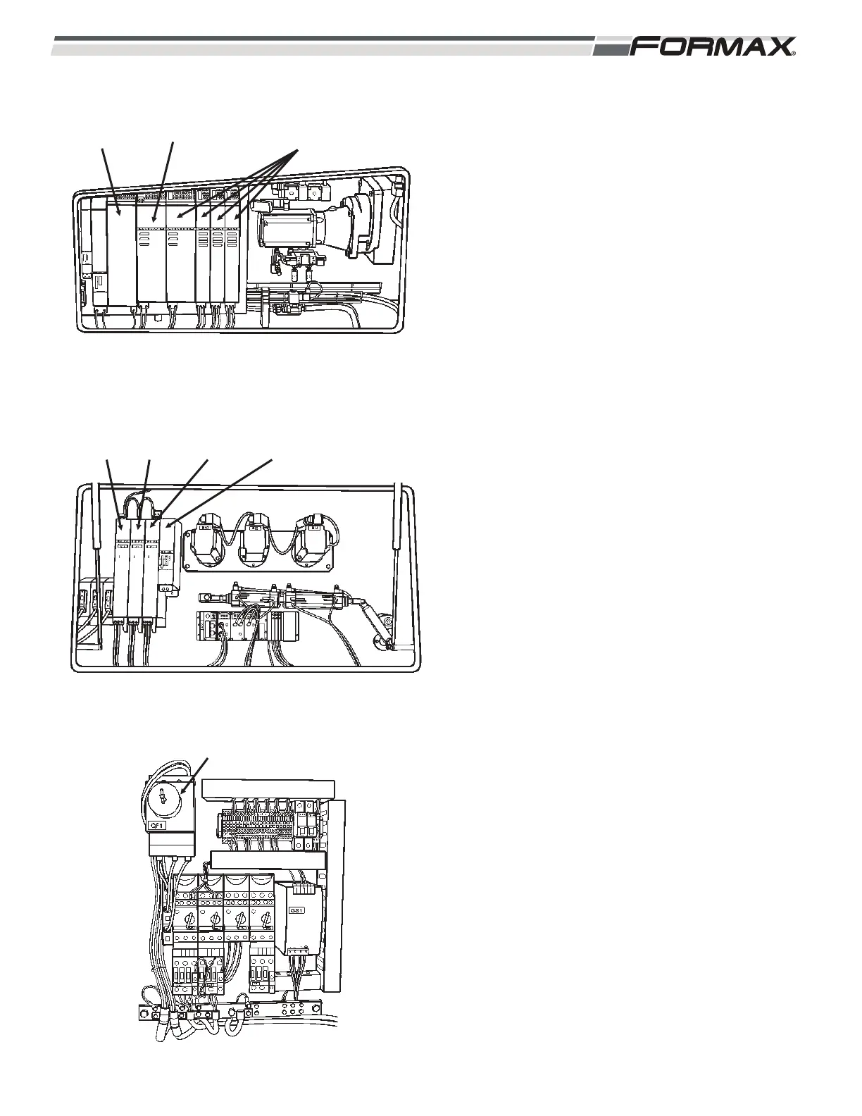
3 PHASE AC SUPPLY VOLTAGE:
1. The “Active Line Module” requires a 3-phase
AC supply voltage. This voltage is supplied
by the main power voltage through the QF1
Breaker. (Illustration 19) The QF1 Circuit
Breaker is a hand operated “On/Off” switch
with Overload Protection and Thermal
Magnetic Release. The QF1 Breaker is also
used for a Lockout/Tagout device.
2. The supply voltage then travels through the
Z1 EMI Filter on wires “L11,” “L21” and “L31.”
The Z1 EMI Filter suppresses noise in the
incoming Supply Voltage and any noise
created by the Servo Drive System.
3. The 3-phase voltage is sent to terminals “U1,”
“V1” and “W1” on the U3 Active Line Module.
ILLUSTRATION 17
U10
SERVO
DRIVE
U11
SERVO
DRIVE
U12
SERVO
DRIVE
ILLUSTRATION 18
U9
MOTION
CONTROLLER
ILLUSTRATION 19
QF1 BREAKER
SERVO
DRIVES
U3 ACTIVE
LINE MODULE
Z1 EMI
FILTER