030712 M4-1
INTRODUCTION
The Powermax3000™ Forming Machine is a fully
integrated Computer Controlled System using a
Profibus Communication Network. This section
explains the electrical and electronic sub-systems
that make up the Powermax3000™ Control System.
Refer to the Electrical Schematic for more
information as you review this section.
ELECTRICAL PRECAUTIONS
At times, it will be necessary to troubleshoot the
electrical systems with the “Power On.” Follow these
precautions when troubleshooting or repairing any
of the Electrical Systems on the Powermax3000™.
ADANGER!
The QF1 Circuit Breaker, the QM Circuit
Controllers, the KM Contactors, the Z1 EMI
Filter, the U3 Active Line Module, the Servo
Drives and the Servo Motors contain
dangerous voltages! (Illustration 2 and 3)
Only Qualified personnel should perform
Service on any of these components!
Always observe the following precautions:
1. Follow your company's
Lockout/Tagout procedures when
performing any maintenance on your
Formax
®
Machine! (Illustration 1)
2. The DC Bus voltage stored in the U3
Active Line Module and the Servo
Drives is in excess of 650 VDC. There
are storage capacitors connected to
the DC Bus that take 5 minutes to
discharge after the power is
disconnected. Wait for the voltage to
drop to “zero” volts before removing
the DC Bus covers or servicing any of
the modules. Refer to the “Servo Drive
Replacement” section for more
information on safely changing a
Servo Drive.
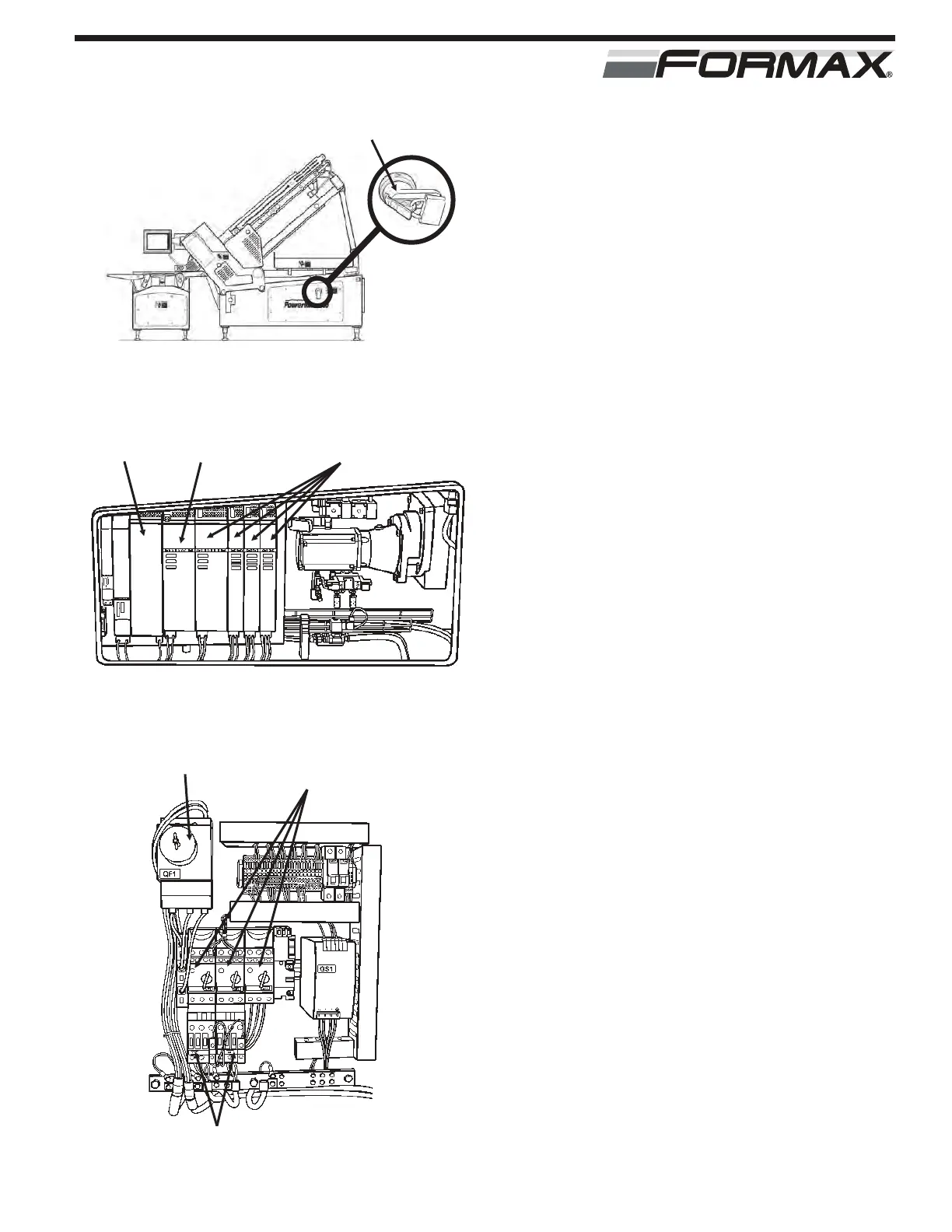
ELECTRICAL - ELECTRONIC
MAIN POWER HANDLE WITH LOCKOUT DEVICE
ILLUSTRATION 1
SERVO
DRIVES
U3 ACTIVE
LINE MODULE
Z1 EMI
FILTER
ILLUSTRATION 2
ILLUSTRATION 3
QF1 BREAKER QM CIRCUIT
CONTROLLER
KM CONTACTORS