M2-10 031914
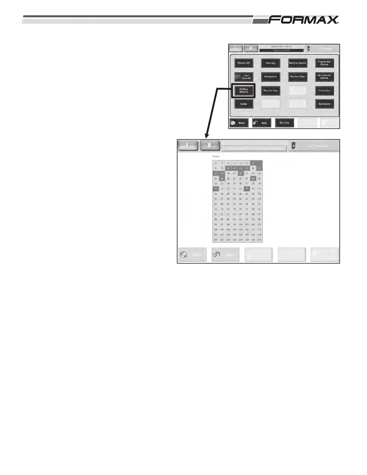
PROFIBUS NETWORK: The “Profibus Network”
screen displays the status of each node in the
Profibus Network. (Illustration 10) Each Node is
indicated by a box around the “Address Setting” of
the Node. When there is good communication, the
Node Boxes will be green. If there is no
communication with one of the nodes, the box will
turn “blue.” There are some optional Nodes that
display and remain “blue” all of the time if not
installed. To identify a Node, touch the Address
Setting” Box. The name of the node will display in a
window on the Touchscreen. The following list
displays the “Addresses” of each Node:
6 = U11 Simotion Controller
7 = ET200S Safety PLC
10 = XS8 Loaf Tray Manifold
11 = XS6 Gripper Housing Manifold
12 = XS5 Loaf Sweep Housing Manifold
13 = XS7 Scale Housing Manifold
15 = AR23 Tray Height Control Manifold
16 = AR15 Scale Driver Control Node
17 = AR30 Upper Infeed Position Control Node
20 = AB Modbus Interface
25 = Takeaway Conveyor I/O Node
30 = Powerloader DP/DP Coupler
40 = External Interface I/O Node
45 = Pneumatic Expansion Manifold
ILLUSTRATION 10