031914 M3-1
INTRODUCTION
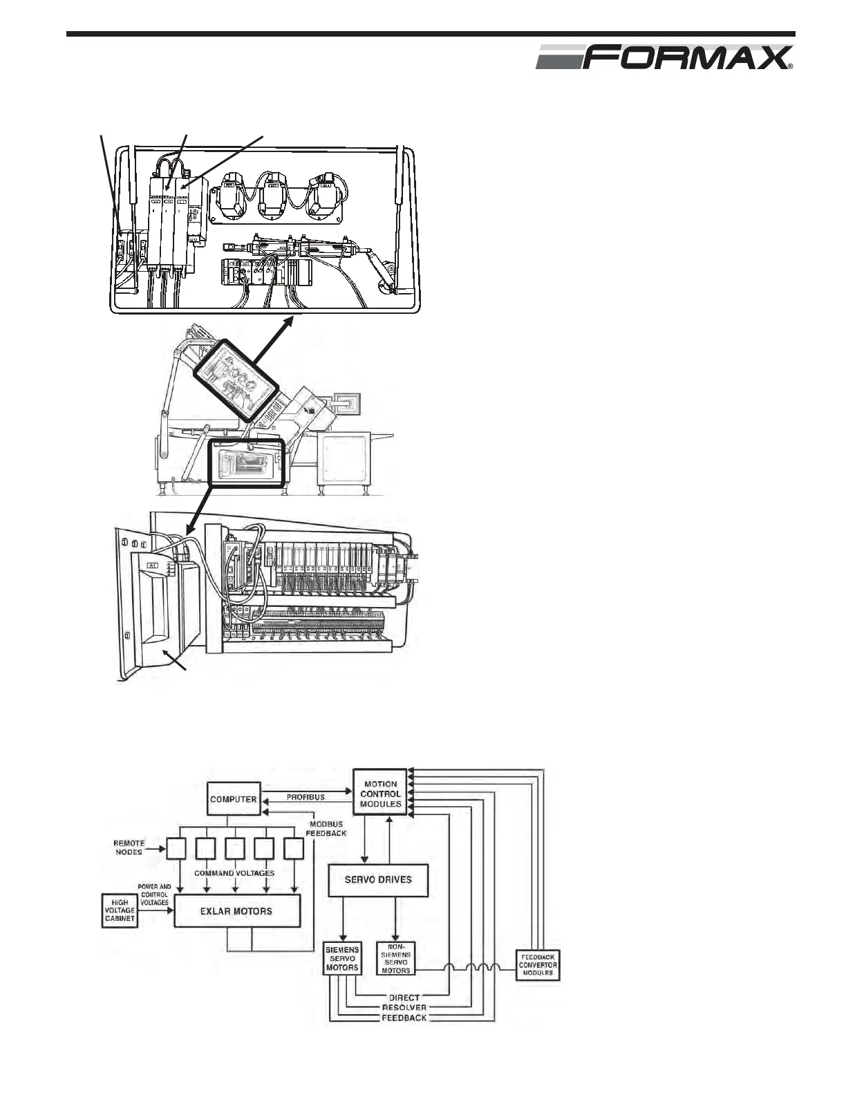
The PowerMax3000™ uses a “Motion
Control System” to accurately control the
speed, direction and response time of the
Servo Motors. (Illustration 1) The Motion
Control System uses a “Closed Loop
Control” system to control the operation of
the Servo Motors. (Illustration 2) The Motion
Control System is made up of the following
major components:
COMPUTER
The Computer determines the sequence
requirements for the Slicer based on the
“Machine Speed,” “Machine Adjustment”
settings and the “Product Code Parameters”
programmed in the Product Code. The
Slicer Computer sends this information over
the Profibus to the U11 Motion Control
Module. The U11 Motion Control Computer
determines the position, direction and speed
requirements of all of the Servo Motors and
send the control signals to the U12 and U13
Motion Controller Modules. The 3 Motion
Control Modules control all of the Servo
Drives and Servo Motors. The Slicer
Computer sends the control signals over the
Profibus to the remote nodes, to control the
Linear and Rotary Actuators.
MOTION CONTROL/SERVO DRIVE SYSTEM
ILLUSTRATION 1
U13 MOTION
CONTROL
MODULE
U11 MOTION
CONTROL
MODULE
U12 MOTION
CONTROL
MODULE
COMPUTER
MOTION CONTROL / SERVO DRIVE SYSTEM
ILLUSTRATION 2