▶
Remove the riser module (1) from PCIe slot 6/7.
▶
Pull the slot bracket with the tubes in the direction of the arrow (2).
▶
Disconnect the control cables from the bottom system board, see Figure 205
and from the top system board, see Figure 206.
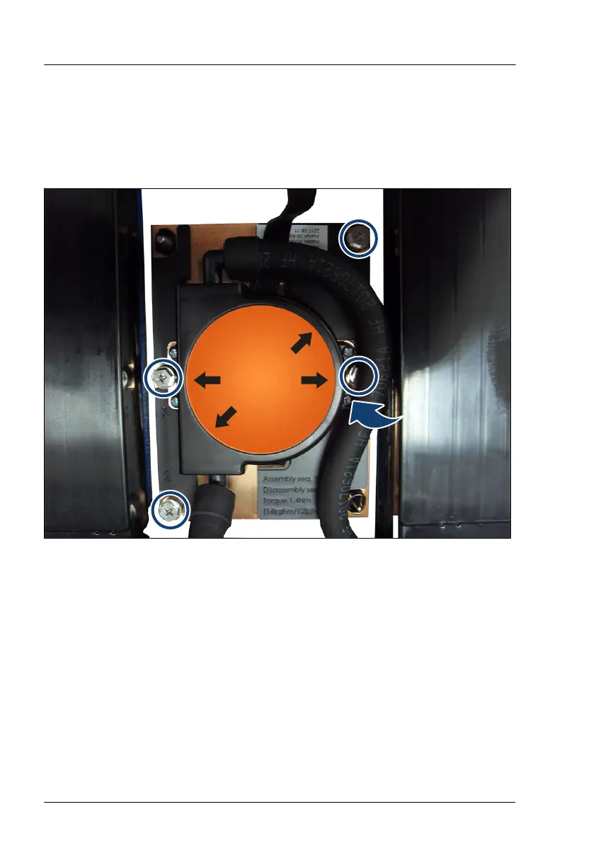
Figure 218: Installing the captive screws of the CPUs
▶
Pull up the tube a little (see arrow) to get access to the screw 3.
▶
Remove the four captive screws for CPU 1/2 in a crossover pattern (1, 2 and
3, 4).
▶
Remove the four captive screws for CPU 3/4 in a crossover pattern (1, 2 and
3, 4).
Liquid cooling (LC)
382 Upgrade and Maintenance Manual RX4770 M5
 Loading...