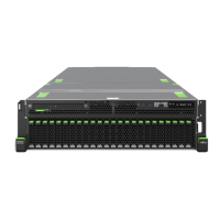
Figure 226: Installing the captive screws of the CPUs
▶
Fasten the four captive screws in a crossover pattern (1 to 4) by hand, by
proceeding as follows:
T
orque: 1.4 Nm (not used in Japan)
▶
First, fasten the captive screws 1 and 2 completely.
▶
Fasten the captive screws 3 and 4 completely.
▶
Pull up the tube a little (see arrow) to get access to the screw 3.
▶
Connect the control cables from the LC device to the bottom system board,
see Figure 205 and to the top system board, see Figure 206.
–
Pump 1 to connector PUMP1
–
Pump 2 to connector PUMP2
–
Pump 3 to connector PUMP3
–
Pump 4 to connector PUMP4
Liquid cooling (LC)
RX4770 M5 Upgrade and Maintenance Manual 389
 Loading...