GE HEALTHCARE PROPRIETARY TO GE
D
IRECTION 55344303-100, REVISION 6 VIVID P3 SERVICE MANUAL
5-20 Section 5-2 - PWA Assy Diagrams
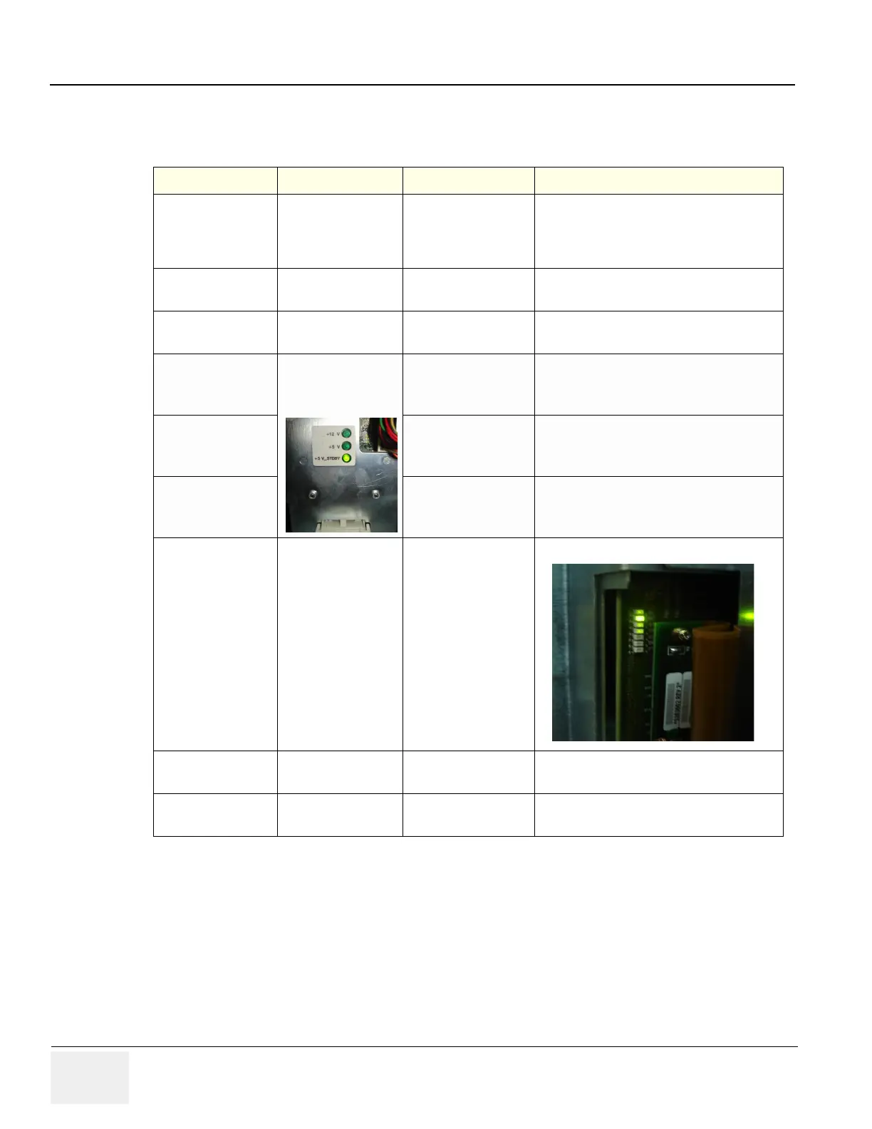
5-2-7-1 Indicator LEDs
Table 5-2 LED Indications
Function Module LED Location LED Color LED Function
Control panel Power switch
Amber When
StandBy, Turns
Green when
switched ON. Main Power activity
RX64 DS1
Green (Normal
Condition) FPGA Config
TX64 DS1
Green (Normal
Condition) FPGA Config
PDB
Green (Normal
Condition)
+5v
Green (Normal
Condition)
+12v
Green (Normal
Condition)
+5v_ Stand by
Connector Board D5
Green (Normal
Condition)
Probe 1 Connected
D6
Green (Normal
Condition) Probe 2 Connected
D7
Green (Normal
Condition) Probe 3 Connected
 Loading...


