GE HEALTHCARE PROPRIETARY TO GE
D
IRECTION 5344303-100, REVISION 3 VIVID P3 SERVICE MANUAL
Chapter 8 Replacement Procedures 8-63
8-6-2 Connector Board Assy 3PP (FRU No. 5314411-2) This is a description on how to
remove and replace the Conn. Board Assy.
8-6-2-1 Tools
• Common Phillips screwdrivers
8-6-2-2 Needed Manpower
• 1 person, 15 minutes
8-6-2-3 Preparations
• Shutdown the system and switch off the main Circuit Breaker at the bottom rear side of the system.
8-6-2-4 Removal Procedure
NOTE: CAUTION An Electronic discharge may damage a component.turn OFF power and wear the
wrist strap before you remove circuit boards. do not un plug the power card to keep ground continuity.
Do not bend or flex the boards when mounting /dismounting each boards surface mount IC boards are
very susceptible to damage from flex/torque.
1) Remove Right cover. Refer section 8-4-1 on page 26 for details on how to remove right cover
2) Remove Left cover. Refer section 8-4-2 on page 28 for details on how to remove right cover
3) Remove Front cover. Refer section Figure 8-27 on page 33 for details on how to remove right cover
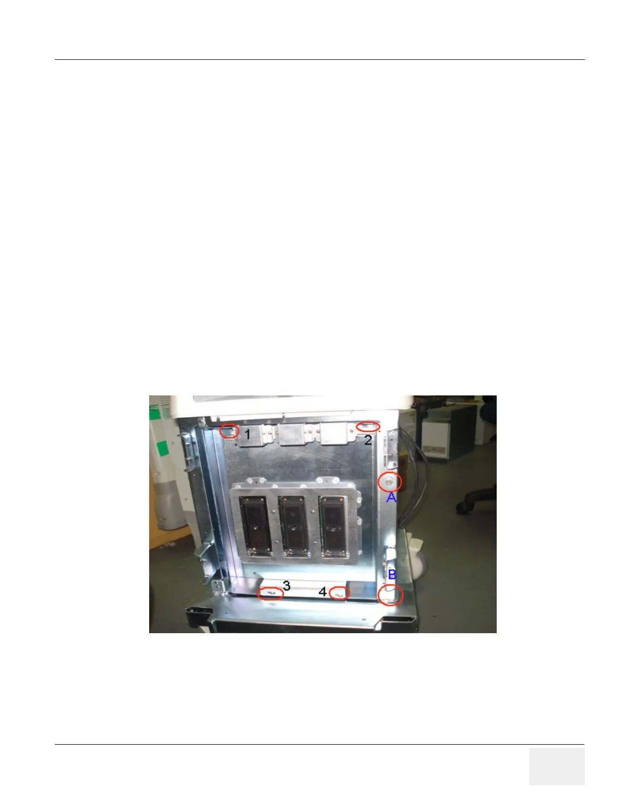
4) Loosen four Screws to remove the connector board and remove the conn board from the system.
Refer Figure 8-54 on page 8-63 . To open the Hinge Door loosen knob screw (A) & (B)
Figure 8-54 Connector Board assembly