GE HEALTHCARE PROPRIETARY TO GE
D
IRECTION 55344303-100, REVISION 6 VIVID P3 SERVICE MANUAL
5-12 Section 5-2 - PWA Assy Diagrams
5-2-1 TMST (cont’d)
• EPLD Programmable logic device
• SH4: Front controlling CPU
• PWR_DIAG: Power diagnostic circuit
• ETX: Card CPU unit
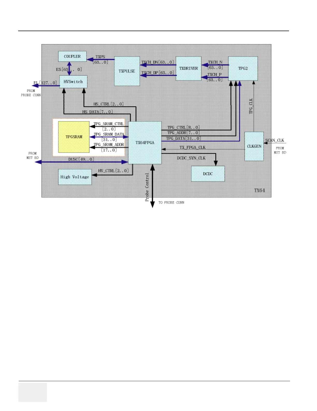
5-2-1-1 Description
This diagram describes the TMST board. It controls the front end of VIVID P3 and also communicate
with PC system through PCI interface.
The main function:
• Generate clock signal and distributing each clock signal.
• Generate DUSC bus cycle.
• Power diagnostics: HV, LV.
• Transmit image raw data (B/CFM/DOP) to PC after assembling packet including header
information.
 Loading...


