GE HEALTHCARE PROPRIETARY TO GE
D
IRECTION 5344303-100, REVISION 3 VIVID P3 SERVICE MANUAL
8-52 Section 8-4 - Mechanicals
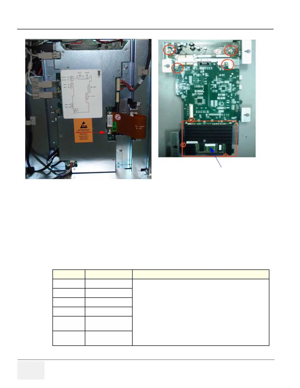
7) Loosen the four screws and slide the MST assembly as shown in Figure A below.
After removing the MST PCB on the other side remove the four screws to remove SOM as shown in
Figure B.
Figure 8-46 MST Assy
8-4-10-6 Mounting procedure
1.) Install the new parts in the reverse order of removal.
8-4-10-7 Functional Checkout Procedure
See Section Functional Test Debrief Script
4-3-1 Power On/Boot Up
Service Manual Direction 5344303-100, Section 8-4-10. Equipment passes all
required tests and is ready for use.
4-3-2 Power Off/ Shutdown
4-3-6 B Mode Checks
4-3-7 M Mode Controls
4-3-8
Color Flow Mode
Checks
4-3-9
Doppler Mode
Checks
SOM
Slide this way to Remove
Fig A
Fig B